• Skip to main content
  • Skip to primary sidebar
  • Skip to footer

Sino Machine Industries

  • Home
  • About Us
  • Industries Served
    • SMI Products Overview
      • SMI Special Steel Products 01
      • SMI Special Steel Products 02
      • SMI Metal Recycling
      • NDT (Non Destructive Testing) service
  • Capabilities
    • Aluminum Industry
      • Aluminum Dross Press
      • Aluminum Dross Cooling Pan
      • Alloy Steel Sow Mold
      • Aluminum Dross Skim Blades and Skim Tools
      • Aluminum Furnace Skimming Tool or Skim blades used for Stirring and Mixing
      • Dross Press & Dross Processing
      • Application of Intelligent Ladle Slag Scraper (Skimming Tools) in steel mills and aluminum mills
      • Transmission Parts
      • The correct combination of the press head and the dross pan
      • 7-9kgs Small Standard Ingot Molds | Moldes de lingotes estándar pequeños de 7-9kgs
      • Comparison between Sow Molds and Ingot Molds
      • Aluminum Dross Transport Equipment
      • Aluminum Dross Recycling Systems
      • Aluminum, Magnesium, Brass, Bronze, Lead, Zinc Ingot Molds
      • Anode steel claw (Electrolytic claw) | Garra de acero del ánodo (garra electrolítica)
      • Anode Steel Yoke
  • eNews
  • Contact Us

Industries We Serve

September 22, 2025 By Sen Liang Leave a Comment

Low Temperature Threaded Check Valve VS Flanged Check Valve


Cryogenic Check Valve Selection: Threaded vs Flanged Design

Selecting the right cryogenic check valve is essential for ensuring safety, sealing reliability, and long-term performance in LNG, liquid nitrogen, and other low-temperature systems.

This guide provides a practical comparison between threaded and flanged check valves, helping engineers and buyers make the right selection.

Threaded vs Flanged Check Valve Comparison
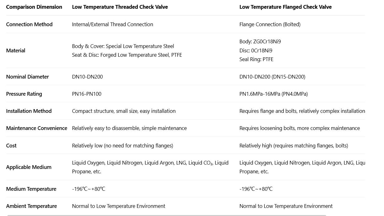
threaded vs flanged cryogenic check valve comparison table

The table above outlines the key differences in connection method, material, pressure rating, and installation requirements.

Key Takeaways

  • Threaded valves are compact and cost-effective for small systems
  • Flanged valves provide stronger connections for high-pressure applications
  • Both types are suitable for cryogenic media such as LNG, liquid oxygen, and liquid nitrogen

Technical Reference (Chinese Version)

threaded vs flanged check valve comparison chinese version

This version is provided for technical reference and communication with Chinese-speaking engineering teams.

Understanding Cryogenic Valve Design Considerations

In cryogenic applications, temperature stratification plays a critical role. Due to the large temperature difference between cryogenic media (as low as -196°C) and ambient conditions, heat transfer creates a temperature gradient across the valve body, stem, and sealing area.

This affects material performance, sealing reliability, and long-term durability.

Important: Actual cryogenic valves may include extended bonnet structures to protect packing and sealing components from extreme low temperatures.

How to Choose the Right Type

Choose Threaded Check Valve When:

  • Pipeline diameter is small
  • Installation space is limited
  • Frequent maintenance is required
  • Project budget is sensitive

Choose Flanged Check Valve When:

  • System pressure is high
  • Pipeline size is larger
  • Higher sealing reliability is required
  • Industrial or critical applications are involved

Typical Applications

  • LNG storage and transport systems
  • Industrial gas plants
  • Cryogenic pipelines
  • Petrochemical facilities

Conclusion

Threaded and flanged cryogenic check valves serve different operational needs. Proper selection depends on system design, pressure rating, installation conditions, and maintenance requirements.

Need Technical Support?

Contact our engineering team for assistance in selecting the right valve solution for your project.
Send Inquiry

Filed Under: Pump & Valve Parts, Valve Bodies & Pump Components, Valves & Pumps Components, Waste Recycling Tagged With: Flanged Check Valve, Threaded Check Valve

March 22, 2025 By Sen Liang Leave a Comment

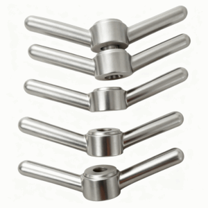
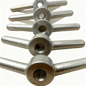
Stainless Steel SS304 SS316 Investment Casting Wing Nut with Machining

Stainless Steel SS304 SS316 Investment Casting Wing Nut with Machining

Stainless Steel SS304 SS316 Investment Casting Wing Nut with Machining
Process: Investment Casting, Precision Machining
Material: Stainless Steel 304, 316, etc.
Keywords: Stainless Steel Wing Nut, SS304 Wing Nut, SS316 Wing Nut, Investment Casting Wing Nut, Machined Wing Nut, Industrial Wing Nut

Tuerca de Ala de Fundición de Inversión en Acero Inoxidable SS304 SS316 con Maquinado
Proceso: Fundición de Inversión, Maquinado
Material: Acero Inoxidable 304, 316, etc.
Palabras Clave: Tuerca de Ala de Acero Inoxidable, Tuerca de Ala SS304, Tuerca de Ala SS316, Tuerca de Ala de Fundición de Inversión, Tuerca de Ala Maquinada, Tuerca de Ala Industrial

Πτερούρα Βίδα Ατσάλινο SS304 SS316 Έκκριση Έκλυσης με Επεξεργασία
Πρόγραμμα: Έκκριση Έκλυσης, Επεξεργασία
Υλικό: Ατσάλινο 304, 316, κ.λπ.
Κλειδιά Λέξεις: Πτερούρα Βίδα Ατσάλινο, Πτερούρα Βίδα SS304, Πτερούρα Βίδα SS316, Πτερούρα Βίδα Έκκρισης Έκλυσης, Πτερούρα Βίδα Επεξεργασμένη, Πτερούρα Βίδα Βιομηχανική

Filed Under: Machined Parts & Custom Castings Tagged With: Wing Nut

March 22, 2025 By Sen Liang Leave a Comment

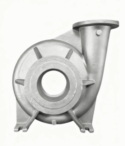
OEM 304/316 Stainless Steel & Alloy Steel Castings for Water Pump Bodies

OEM 304/316 Stainless Steel & Alloy Steel Castings for Water Pump Bodies
We (SMI) specialize in OEM precision castings (0.1kg to 200kg per piece), CNC machining parts, and sand castings (1kg to 10 metric tons per piece), all customized to your exact specifications. Our high-quality castings are engineered for the fluid flow industry, automotive, agricultural equipment, oil & gas, mining, construction, metallurgy, and coal mining machinery.

Fundición de Acero Aleado y Acero Inoxidable 304/316 OEM para Cuerpos de Bombas de Agua
Nos especializamos en fundición de precisión OEM (de 0.1kg a 200kg por pieza), mecanizado CNC y fundición en arena (de 1kg a 10 toneladas métricas por pieza), todos personalizados según sus especificaciones exactas. Nuestras fundiciones de alta calidad están diseñadas para la industria de flujo de fluidos, automoción, equipos agrícolas, petróleo y gas, minería, construcción, metalurgia y maquinaria para minería de carbón.

Χυτεύσεις OEM από Ανοξείδωτο Ατσάλι 304/316 & Κράμα Ατσαλιού για Κουφώματα Αντλιών Νερού
Ειδικευόμαστε σε χυτεύσεις υψηλής ακρίβειας OEM (0.1kg έως 200kg ανά τεμάχιο), εξαρτήματα μηχανικής επεξεργασίας CNC και χυτεύσεις σε άμμο (1kg έως 10 μετρικούς τόνους ανά τεμάχιο), όλα προσαρμοσμένα ακριβώς στις προδιαγραφές σας. Οι χυτεύσεις μας υψηλής ποιότητας σχεδιάζονται για τη βιομηχανία ροής ρευστών, αυτοκινήτων, γεωργικού εξοπλισμού, πετρελαίου και φυσικού αερίου, εξόρυξης, κατασκευών, μεταλλουργίας και μηχανημάτων εξόρυξης άνθρακα.

سبائك الصلب المقاوم للصدأ 304/316 OEM والمسبوكات الفولاذية لهياكل مضخات المياه
نحن متخصصون في مسبوكات OEM الدقيقة (من 0.1 كجم إلى 200 كجم للقطعة)، وأجزاء التشغيل الآلي باستخدام الحاسب الآلي، والمسبوكات الرملية (من 1 كجم إلى 10 أطنان متريكة للقطعة)، كلها مخصصة وفقًا لمواصفاتك الدقيقة. تم تصميم مسبوكاتنا عالية الجودة لصناعة تدفق السوائل، والسيارات، والمعدات الزراعية، والنفط والغاز، والتعدين، والبناء، والاستخلاص المعدني، وآلات تعدين الفحم.

Filed Under: Machined Parts & Custom Castings Tagged With: Water Pump Bodies

March 14, 2025 By Sen Liang Leave a Comment

Aluminium Plant vs Steel Plant Skimming Tools: Key Differences Explained | SMI Technical Guide

A Complete Technical Comparison: Aluminium Plant vs Steel Plant Skimming Tools

📁 Technical Guides — Aluminium Casting; ✍ SMI Technical Team; 🕐 12 min read
 
Skimming tools are consumable assets that directly affect melt quality, metal recovery, and casthouse throughput — yet the requirements in an aluminium smelter and a steel plant are so fundamentally different that a tool designed for one environment will fail in the other. This guide compares skimming blades, skimming arms, dross pans, and deslagging systems across both industries, covering design rationale, material selection, operating temperature, furnace-specific geometry, and efficiency benchmarks. Understanding these differences is essential for engineers specifying tools, and for procurement teams evaluating suppliers.
Table of Contents

  1. Why Aluminium and Steel Plants Need Different Tools
  2. Primary vs Secondary Aluminium: An Important Distinction
  3. Furnace Type and Door Geometry: How It Shapes the Tool
  4. Skimming Blade Design: Aluminium vs Steel
  5. Skimming Arms and Mechanised Systems
  6. Dross Pans and Slag Pans
  7. Material Selection and Coating
  8. Skimming Efficiency and Dross Recovery
  9. Master Comparison Table
  10. Tool Selection Quick Reference
  11. Frequently Asked Questions

1. Why Aluminium and Steel Plants Need Entirely Different Skimming Tools

The word “skimming” describes the same basic act in both industries — removing the oxide and impurity layer from the surface of molten metal. But beyond that surface similarity, the two applications differ on almost every dimension that matters for tool design.

🔵 Aluminium Plant
  • Melt surface temperature: 700–900°C
  • Dross density: lower than the melt — floats freely
  • Dross type: aluminium oxide (Al₂O₃), semi-solid to viscous
  • Chemical aggressiveness: low — minimal attack on iron tools
  • Tool priority: wide coverage, metal recovery through perforations, low iron contamination risk
  • Skimming force required: moderate
🔴 Steel Plant
  • Melt surface temperature: 1,400–1,650°C
  • Slag density: high — sits as a heavy viscous layer
  • Slag type: silicates, oxides — aggressive, corrosive, sparking
  • Chemical aggressiveness: very high — dissolves standard steels rapidly
  • Tool priority: extreme heat resistance, high force, chemical durability
  • Skimming force required: high to very high
🔑 Core Principle

The operating temperature in a steel plant (up to 1,650°C) is nearly twice the temperature in an aluminium smelter (700–900°C). This single fact drives every downstream difference in material grade, tool geometry, handle length, coating type, and automation level. No aluminium skimming tool — regardless of how it is coated — can survive in a steelmaking environment without a complete redesign.

2. Primary vs Secondary Aluminium Smelters: An Important Distinction

Before comparing aluminium versus steel, it is important to note that not all aluminium plants are the same. The skimming tool requirements differ significantly between primary aluminium smelters (which produce virgin aluminium via electrolysis) and secondary aluminium plants (which re-melt aluminium scrap).

Factor Primary Aluminium Smelter Secondary (Recycled) Aluminium Plant
Raw material Alumina (Al₂O₃) from bauxite, via Hall-Héroult electrolysis Aluminium scrap: UBC, profiles, castings, mixed grades
Dross type White dross — 50–80% metallic Al; recoverable; lower oxide content Black dross — 10–30% metallic Al; coatings, oils, salts; harder to process
Furnace types Reverberatory casting furnaces; large electrolytic cells (no skimming needed in cells) Reverberatory furnace; Tilting Rotary Furnace (TRF) for contaminated scrap
Skimming tool design Wide flat rake; long handle (2.5–3.5 m); mechanised skimming arms at large facilities Heavier-duty tools; perforated designs for metal recovery; curved scrapers for TRF drum opening
Iron contamination risk Low — brief contact; primary melt is pure Higher — prolonged contact raises Fe contamination; coated or SiC tools preferred
Dross press relevance High — white dross has high metallic Al recovery value High — but requires more sophisticated processing for black dross
⚠ Important for Tool Specification

Always establish whether the customer is a primary or secondary smelter before specifying tools. A secondary plant with a tilting rotary furnace (TRF) needs entirely different tool geometry — shorter handle, curved head profile matched to the drum opening — compared to a primary plant’s large reverberatory furnace requiring long-handle wide rakes. Sending the wrong tool is a common and costly procurement mistake.

3. Furnace Type and Door Geometry: How the Furnace Shapes the Tool

Skimming tool geometry is not a free design choice — it is directly constrained by the furnace opening through which the tool must operate. This is one of the most commonly overlooked factors in tool specification.

3.1 Aluminium Plant Furnace Types

Reverberatory Furnace

The reverberatory furnace is the dominant melting and casting furnace in both primary and secondary aluminium. It features a wide, flat bath with access through a front or side door (typically 0.8–1.5 m wide). This wide opening allows long-handle rakes and ladles to reach the full bath width. The flat bath geometry favours a shallow tool angle and wide head profile.

Tilting Rotary Furnace — TRF

The TRF is the dominant technology for processing contaminated and mixed scrap in secondary aluminium. The furnace is a rotating drum that tilts to discharge slag and metal. Access is exclusively through the drum end opening (typically Ø500–800 mm) — a restricted circular aperture that eliminates the use of wide, flat rakes entirely.

★ Proprietary Technology Note

The TRF’s drum geometry, tilting angle mechanism, internal refractory lining, and flux injection system are typically proprietary to the furnace OEM. Key OEM suppliers include Hertwich Engineering (Austria), Gautschi Engineering (Switzerland), StrikoWestofen (Germany), JASPER GmbH (Germany), and Tenova (Italy). Tool suppliers must design skimming tools to fit OEM-specified drum inner diameters without replicating protected geometric designs.

3.2 Steel Plant Furnace Types

Furnace Type Opening / Access Point Slag Volume Skimming Tool Implication
BOF (Basic Oxygen Furnace / Converter) Large top vessel mouth, Ø4–8 m; tap-hole in base/side 100–130 kg/t steel Crane-mounted large slag pusher, custom to vessel diameter; ZG40Cr25Ni20 steel
EAF (Electric Arc Furnace) Water-cooled slag door in furnace shell (~300–500 mm slot); EBT bottom tap 60–80 kg/t Angled scraper matched to slag door slot width; high-alloy steel + ceramic coating
LF (Ladle Furnace) Top electrode openings; side slag door (smaller) 15–30 kg/t (secondary refining slag) Compact ladle skimmer; 3–5 m handle; MgO-coated tip; hand or mechanised
★ Proprietary Technology Note — Steel

The EBT (Eccentric Bottom Tapping) system is patented in various configurations by Primetals Technologies and SMS Group. The tap-hole geometry and sand-filling system are proprietary. The Consteel® continuous scrap charging system is patented by Intersteel Technology Inc. Tool suppliers must not replicate these protected systems.

4. Skimming Blade Design: Aluminium vs Steel Plant

The skimming blade (also called the working head, skim paddle, or scraper head) is the tool element in direct contact with the melt surface. Its profile, material, and geometry are entirely application-specific.

4.1 Aluminium Plant Skimming Blade Profiles

Because aluminium dross floats on the melt surface and is relatively low-density, the primary design goal is maximum surface coverage at minimum contact depth — keeping the blade skimming the dross layer without disturbing the molten aluminium below.

  • Wide flat rake: 400–600 mm wide; shallow angle entry; removes dross from large bath areas in a single pass. Standard tool for reverberatory furnaces.
  • Perforated skimmer ladle: Allows molten aluminium to drain back through perforations (typically Ø15–25 mm) while retaining the dross. Critical for maximising metal recovery from white dross before it reaches the dross pan.
  • Push plate: A flat paddle used for the final bath cleaning pass before tapping, pushing residual dross to one side.
  • Curved end scraper (TRF-specific): Profile matched to the drum inner diameter (Ø500–800 mm); shorter and heavier-duty; designed to operate through the restricted drum end opening.

4.2 Steel Plant Deslagging Blade / Scraper Profiles

Steel plant slag is dense, viscous, and highly corrosive at extreme temperatures. The blade must apply significant force to push or scrape the slag layer while surviving the chemical and thermal environment without rapid failure.

  • BOF slag pusher: Large flat or angled blade, custom to converter vessel diameter; typically crane-mounted; designed for single-pass slag displacement before and after tapping.
  • EAF slag door scraper: Angled blade profiled to fit through the water-cooled slag door slot (300–500 mm); must clear the door aperture at working angle.
  • LF ladle skimmer: Compact head; MgO-coated working surface; designed for thin synthetic slag layer removal without disturbing the refined steel below.
✅ Design Principle Contrast

Aluminium skimming blades are designed for coverage and drainage — moving large surface areas of low-density dross while allowing liquid metal to return to the melt. Steel plant deslagging blades are designed for force and durability — pushing dense, sticky, high-temperature slag with sufficient mechanical force to clear the furnace or ladle surface.

5. Skimming Arms and Mechanised Deslagging Systems

A skimming arm is the structural assembly that holds, positions, and drives the skimming blade. The degree of automation — from manual poles to fully robotic systems — varies significantly between aluminium and steel applications.

5.1 Aluminium Plant Skimming Arms

In aluminium casthouses, skimming arms range from simple hand-operated poles to fully mechanised multi-axis arms mounted on the furnace platform.

Arm Type Application Handle Length Key Features
Manual pole (carbon steel) Small reverberatory or induction furnace 1.5–3.5 m Simple, low cost; operator controls angle and pressure manually
Semi-mechanised push/pull arm Medium reverberatory furnace 2.5–4.0 m Mechanical assist for extension/retraction; reduces operator fatigue
Mechanised skimming arm Large primary smelter casting furnaces N/A — machine-mounted Hydraulic or electric drive; 2–4 axes of motion; operator-controlled from console
TRF end-door scraper set Secondary Al tilting rotary furnace ≤1.5 m (restricted by drum opening) Curved profile; heavy-duty; matched to drum inner Ø; shorter stroke

5.2 Steel Plant Deslagging Arms and Machines

Steel plant deslagging systems are significantly more mechanised, driven by the much higher temperatures and forces involved. Manual operations are the exception rather than the rule at large facilities.

System Type Application Key Specifications
Overhead crane-mounted slag pusher BOF / Converter tapping area Custom to vessel diameter (4–8 m); ZG40Cr25Ni20; consider water-cooled variants
EAF slag door scraper EAF slag door opening Must fit through 300–500 mm slag door slot; high-alloy steel + ceramic coating; water-cooled handle option
Ladle deslagging machine LF ladle furnace, torpedo car 4-axis full hydraulic drive (lift, tilt, swing, extension); 2,000 mm stroke; 15 kN force; handles ≤50T ladles; on-site console or optional remote operation
Automated robotic slag raker Large EAF / high-automation BOF facilities Fully automated with machine vision; reduces operator exposure; large capital investment
🔑 Ladle Deslagging Machine — Key Capability

The hydraulic ladle deslagging machine used in steelmaking represents a significant step up in engineering complexity from aluminium skimming arms. A full hydraulic system with 4 independent motion axes (vertical lift 300 mm, extension 2,000 mm, tilt ±15°, swing ±20°) delivers a deslagging force of 15 kN at up to 16 MPa system pressure — capabilities that would be entirely over-specified and unnecessary in an aluminium casthouse, where dross is far lighter and furnace temperatures are hundreds of degrees lower.

6. Dross Pans and Slag Pans: Collection Vessel Differences

The dross pan (or slag pan) is the receiving vessel into which skimmed dross or slag is deposited after removal from the furnace. Like the skimming tools themselves, the requirements diverge significantly between aluminium and steel applications.

6.1 Aluminium Dross Pan

In an aluminium casthouse, dross pans are typically cast iron vessels sized to fit beneath the furnace door opening. Their primary functions are:

  1. Receive hot dross directly from the skimming blade during the skimming operation
  2. Retain the heat of the dross (critical — see dross press efficiency note below)
  3. Transport the dross to the dross press within the shortest possible time
  4. Allow initial drainage of any free liquid aluminium back through perforations (on perforated pan designs)

Key specifications for aluminium dross pans:

  • Material: Cast iron (HT200–HT300) or ductile iron (QT450); heat-resistant alloy steel for high-throughput operations
  • Coating: Refractory wash or boron nitride (BN) release coating to prevent aluminium adhesion and extend service life
  • Typical service life: 6–18 months (primary smelter conditions)
  • Design consideration: Thermiting dross (dross that re-ignites due to exothermic reaction) can warp and bow standard pans — proprietary alloy formulations significantly extend service life under thermiting conditions
⚠ Critical Efficiency Note — Time to Press

The time between skimming the dross into the pan and feeding it into the dross press is the single most important variable in aluminium recovery from dross. White dross at over 600°C contains liquid aluminium that separates easily under press pressure. Below 400°C, the aluminium has solidified and recovery drops sharply. Every 10 minutes of cooling represents approximately 30–50°C of temperature loss and a measurable reduction in recovery. See our dross press guide for full recovery rate analysis.

6.2 Steel Plant Slag Pan

Steel plant slag pans handle far larger volumes of far more aggressive material. Key differences from aluminium dross pans:

  • Size: Much larger (tonnes per pour, not kilograms) — handled by overhead crane, not manually transported
  • Material: High-alloy steel, sometimes water-cooled shells for high-throughput applications
  • Temperature: Must handle initial contents at 1,400°C+
  • Recovery: Steel slag is not typically pressed for metal recovery in the same way; the focus is disposal or slag valorisation (cement, road base)
  • Service life: Shorter per cycle, but handled with crane systems that reduce physical wear compared to manual aluminium pans

7. Material Selection and Protective Coatings

Component Aluminium Plant Steel Plant Rationale for Difference
Working head / blade Cast iron HT200–HT300
or Ductile iron QT450-10
ZG40Cr25Ni20 high-alloy heat-resistant steel
or ceramic-coated steel
Steel plant operating temperature would destroy cast iron within minutes; high-Cr alloys resist slag attack and thermal shock at 1,400–1,650°C
Handle / shank Carbon steel tube or bar (S235/Q235) Carbon steel with heat-resistant coating; water-cooling available for extreme applications Radiant heat from steel furnaces requires active cooling for long handles; aluminium furnace handles can be standard steel
Protective coating Refractory wash
or Boron Nitride (BN) release agent
Plasma-sprayed ZrO₂ or Al₂O₃ ceramic; some proprietary coatings BN coating prevents aluminium adhesion and extends life 30–50%; steel plant coatings must survive far higher thermal and chemical load
Dross / slag pan Cast iron HT200–HT300; some ceramic-lined variants High-alloy steel; water-cooled shell variants for BOF Temperature and slag aggressiveness drive material choice; aluminium dross pan requires good thermal retention, not just thermal resistance
LF / ladle deslagging tip N/A MgO-coated working tip preferred MgO resists attack by basic (high-CaO) LF synthetic slag; no equivalent requirement in aluminium
✅ Boron Nitride (BN) Coating for Aluminium Tools

In aluminium casthouses, a boron nitride release coating on both skimming blades and dross pans is the most cost-effective life extension measure available. BN acts as a non-wetting barrier between the iron surface and molten aluminium, reducing metal adhesion and dross sticking. A well-applied BN coating can extend skimming tool life by 30–50% and significantly reduces the iron contamination risk in primary aluminium operations. Reapplication frequency depends on tool cycling rate and bath temperature.

8. Skimming Efficiency and Dross Recovery: What the Numbers Actually Mean

Efficiency metrics for skimming tools are often misunderstood — particularly in the context of aluminium dross recovery. The numbers cited in different sources appear inconsistent because they measure fundamentally different things.

8.1 Aluminium Dross Recovery: Three Different Metrics

There are three distinct ways to express recovery performance in aluminium dross management. Confusing them is the source of most disagreement about “recovery rates.”

Metric Formula Typical Value What It Measures
① Dross Al content Metallic Al in dross ÷ Total dross weight White dross: 50–80%
Black dross: 10–30%
Input material quality — not a recovery rate
② Press equipment efficiency Al pressed out ÷ Al originally in the dross 60–90% (ideal conditions) How well the press extracts Al from what it receives
③ System recovery rate Total Al pressed out ÷ Total dross weight fed in 15–60% (real plant conditions) Net Al yield per kg of dross — the number that drives ROI

The widely cited “70–90%” figure in industry literature refers to Metric ② under ideal conditions — fresh hot white dross processed immediately. The real-world figure of 15–35% (Metric ③) reflects mixed dross types, cooling losses, and operational variables. Both numbers are correct — they simply measure different things.

8.2 Numerical Example: How Dross Temperature and Type Drive the Result

Scenario A — Primary smelter, hot white dross, pressed immediately (ideal)
Feed into press: 1,000 kg | Al content (Metric ①): 70% = 700 kg metallic Al
Press equipment efficiency (Metric ②): 85%
Al pressed out: 700 × 85% = 595 kg
System recovery rate (Metric ③): 595 ÷ 1,000 = 59.5%
Scenario B — Primary smelter, real mixed-operations conditions (~33% reported by major plants)
Feed into press: 1,000 kg | Mixed dross Al content: ~50% = 500 kg metallic Al
Press efficiency (cooling + mixed feed): ~72%
Al pressed out: 500 × 72% = 360 kg
System recovery rate (Metric ③): 360 ÷ 1,000 = 36%
Scenario C — Secondary smelter / mixed black dross conditions (15–25% reported field range)
Feed into press: 1,000 kg | Mixed black dross Al content: ~25% = 250 kg metallic Al
Press efficiency (cold, high-impurity dross): ~65%
Al pressed out: 250 × 65% = 163 kg
System recovery rate (Metric ③): 163 ÷ 1,000 = 16.3%
⚠ Key Rule: Never Mix White and Black Dross Before Pressing

Mixing white dross (50–80% Al) with black dross (10–30% Al) before pressing directly dilutes the feed and reduces Metric ③. The loss is not due to the press — it is a feedstock management failure. Segregate white dross and black dross from the moment of skimming, route them through separate processing paths, and press white dross as hot as possible.

8.3 Steel Plant Deslagging Efficiency

In steelmaking, the efficiency metric for deslagging is different in character. The goal is not metal recovery from slag (as in aluminium) but rather:

  • Slag carry-over reduction: Minimising the amount of slag transferred into the ladle during tapping — directly affects steel cleanliness and downstream refining costs
  • Clean tapping: EBT systems in EAF and slag detection systems in BOF are specifically engineered to minimise slag carry-over
  • Deslagging completeness: In LF operations, removing the slag layer from the ladle surface before casting prevents inclusions in the final product

For steel plant ladle deslagging machines specifically, the key efficiency indicators are deslagging force (kN), stroke coverage, and the ability to operate continuously for ≥10 minutes without component deformation — not a metal recovery percentage.

9. Master Comparison Table: Aluminium vs Steel Skimming Tools

Parameter Aluminium Plant Steel Plant
Operating temperature 700–900°C (melt surface) 1,400–1,650°C (melt surface)
Dross / slag characteristics Low-density Al₂O₃ dross; semi-solid; floats on melt; non-aggressive to iron High-density silicate/oxide slag; dense; corrosive; aggressive; sparking at contact
Primary furnace types Reverberatory furnace (wide side/front door); Tilting Rotary Furnace (drum end opening, Ø500–800 mm); induction furnace BOF (top vessel mouth Ø4–8 m); EAF (slag door slot 300–500 mm); LF ladle furnace (top electrode + side door)
Skimming blade profile Wide flat rake (400–600 mm); perforated ladle; push plate; curved scraper (TRF-specific) Large flat pusher (BOF); angled scraper (EAF door); compact ladle head (LF); claw-type (ladle deslagging machine)
Working head material Cast iron HT200–HT300 or Ductile iron QT450-10 ZG40Cr25Ni20 / ZG35Cr28Ni16 high-alloy heat-resistant steel; ceramic-coated; water-cooled copper tips (extreme applications)
Handle length 1.5–3.5 m (manual); machine-mounted for large furnaces 2.0–6.0 m (manual); crane-mounted or machine-arm for large furnaces
Protective coating Refractory wash; Boron Nitride (BN) release agent — extends life 30–50% Plasma-sprayed ZrO₂ or Al₂O₃ ceramic; MgO (LF ladle tips); proprietary coatings
Skimming force required Moderate — dross floats, low resistance High to very high — dense slag requires substantial force
Automation level Manual → semi-auto → mechanised arm; large primary plants use full mechanised arms Manual → semi-auto → fully mechanised machine; large EAF plants use robotic slag rakers
Dross / slag collection vessel Cast iron dross pan (portable, manually transported); some ceramic-lined Large alloy steel slag pan (crane-handled); water-cooled variants for BOF
Metal recovery from dross / slag High priority: dross press recovers 15–60% Al (Metric ③) depending on dross type and temperature Not primary objective; focus is slag carry-over reduction and steel cleanliness
Typical working head service life 3–12 months (primary Al); 1–3 months (secondary Al) 2–8 weeks in BOF/EAF environment
Iron contamination risk Moderate — must be managed (BN coating; brief contact time; material selection) Not applicable — iron-based tools acceptable at steel temperatures
Key consumable driver Thermal cycling fatigue; dross adhesion; oxidation of iron surface Extreme thermal shock; slag chemical attack; mechanical impact at high temperature

10. Skimming Tool Selection Quick Reference

Use the guide below to identify the correct tool type for a given application. The most common specification errors arise from applying aluminium plant tools to rotary furnaces, or comparing performance numbers without establishing the underlying dross type and operating conditions first.

Application Correct Tool Type Key Specification Parameters
Al Primary smelter — reverberatory casting furnace Wide flat rake + optional mechanised arm Head: 400–600 mm wide; Handle: 2.5–3.5 m; Material: HT250 cast iron + BN coating
Al Secondary smelter — reverberatory furnace (clean scrap) Perforated skimmer ladle + flat rake Perforations: Ø15–25 mm; Handle: 2.0–3.0 m; Material: QT450 ductile iron
Al Secondary smelter — Tilting Rotary Furnace (TRF) Short curved end-door scraper set Head profile matched to drum inner Ø; Handle: ≤1.5 m; Heavy-duty construction; BN or refractory wash
Al All aluminium operations — dross collection Cast iron dross pan Sized to furnace door opening; thermiting-resistant alloy for secondary ops; refractory wash coating
Steel BOF / converter tapping area Crane-mounted slag pusher ZG40Cr25Ni20 or water-cooled; custom to furnace vessel diameter
Steel EAF slag door Angled scraper for water-cooled slag door Fit through door slot (~300–500 mm); high-alloy steel + ceramic coating
Steel LF ladle furnace / torpedo car Hydraulic ladle deslagging machine 4-axis full hydraulic; 2,000 mm stroke; 15 kN force; ≤50T ladle; voltage configurable for international installations

11. Frequently Asked Questions

What is the main difference between aluminium and steel plant skimming tools?
The fundamental difference is operating temperature and slag/dross characteristics. Aluminium skimming tools operate at 700–900°C against low-density aluminium oxide dross using cast iron rakes and ladles. Steel plant deslagging tools must withstand 1,400–1,650°C against dense, highly corrosive silicate slag, requiring high-alloy heat-resistant steel and entirely different blade geometry and drive systems.
Why do aluminium plants and steel plants use different skimming arm designs?
Aluminium smelters use wide, low-angle arms to rake low-density dross floating on the melt surface, often with mechanised arms for large reverberatory furnaces. Steel plants require high-force slag scrapers — sometimes crane-mounted or robotic — to push dense, viscous slag at extreme temperatures. The mechanical loads and thermal demands are in an entirely different category.
What material is used for aluminium skimming blades versus steel plant deslagging blades?
Aluminium skimming blades use cast iron (HT200–HT300) or ductile iron (QT450-10) with refractory wash or boron nitride coating. Steel plant deslagging blades require high-alloy heat-resistant steel such as ZG40Cr25Ni20 or ZG35Cr28Ni16, and often plasma-sprayed ceramic coatings, to survive the far higher temperatures and chemically aggressive slag environment.
What is a dross pan and how does it differ between aluminium and steel operations?
In aluminium operations, dross pans are cast iron vessels that receive skimmed dross and transport it quickly to the dross press — heat retention is critical for metal recovery. In steel operations, slag pans are much larger crane-handled vessels handling tonne-scale slag volumes at steelmaking temperatures; the focus is safe containment and disposal, not metal recovery by pressing.
Does a primary aluminium smelter need different skimming tools compared to a secondary aluminium plant?
Yes, significantly. Primary smelters use large reverberatory furnaces with wide doors, favouring long-handle wide rakes and mechanised arms. Secondary plants — especially those with tilting rotary furnaces (TRF) — require shorter curved scrapers matched to the drum opening. The dross type also differs: primary white dross (50–80% metallic Al) vs secondary black dross (10–30% metallic Al), which affects both tool design and downstream dross press economics.
Why is the aluminium dross recovery rate reported as both 70–90% and 15–35% — which is correct?
Both figures are correct — they measure different things. The 70–90% figure is the press equipment’s extraction efficiency relative to the metallic aluminium already present in the dross, measured under ideal conditions with fresh hot white dross. The 15–35% figure is the system recovery rate: total aluminium pressed out divided by total dross weight fed in, across real plant conditions with mixed dross types and temperature variations. The second figure is what drives actual plant ROI.

Specify the Right Skimming Tool for Your Operation

SMI has supplied skimming tools, dross pans, sow molds, ingot molds, and dross press equipment to aluminium smelters and metal recycling operations globally for nearly 30 years. Our engineering team can help you identify the correct tool specification for your furnace type, dross characteristics, and operating conditions.

Contact our Engineering Team →

inquiry@sinomachine.org · Technical Datasheets Available on Request

Related Technical Guides

  • Steel Grade Selection for Aluminium Ingot Molds — Technical Guide
  • Shrinkage Allowance in Aluminium Ingot Mold Design
  • SMI Aluminium Ingot Molds, Sow Molds and Dross Pans
  • Ingot Molds for Aluminium, Magnesium, Brass, Bronze, Lead, Zinc

Trademark & Intellectual Property Notice: All brand names, trademarks, trade names, and proprietary technology designations referenced in this article — including but not limited to Hertwich, Gautschi, StrikoWestofen, JASPER, Tenova, Primetals Technologies, SMS Group, Wagstaff, EBT, Consteel, ELYSIS, and all other names mentioned — are the property of their respective owners. All rights reserved to their respective owners. These references are made solely for the purpose of technical identification, industry education, and factual description of publicly documented equipment and processes. Such references do not constitute, imply, or suggest any commercial relationship, business affiliation, partnership, endorsement, or sponsorship between the referenced companies and Sino Machine Industries.

No Legal or Engineering Advice: Information regarding proprietary, patented, or patent-pending technologies is provided for general informational and educational purposes only. Sino Machine Industries makes no representation or warranty, express or implied, as to the accuracy, completeness, or current status of any patent or intellectual property information presented. Engineers and procurement professionals should independently verify all intellectual property status, applicable standards, and regulatory requirements before incorporating any specific design, process, or material into a project. This article does not constitute legal, engineering, or procurement advice.

Technical Data: Performance figures, benchmark data, and operational parameters presented in this article are derived from publicly available industry literature, published academic sources, and generalised operational experience. Actual performance in any specific installation will vary based on site conditions, equipment configuration, operating practices, and raw material characteristics. Sino Machine Industries accepts no liability for decisions made on the basis of general benchmark data presented herein.


Filed Under: Aluminium Casting, Aluminum Industry Tagged With: aluminium dross removal, aluminium skimming tools, casthouse equipment, dross pan, Dross Press, furnace tools aluminium, ladle deslagging, reverberatory furnace skimming, rotary furnace, skimming arm, skimming blade, steel plant deslagging tools, steel slag removal

March 12, 2025 By Sen Liang Leave a Comment

What Is a Drain Sow Mold? Uses, Design & Key Specifications

Drain Sow Molds Explained: Purpose, Design Features and How to Specify the Right One

Drain sow molds are a specialised subset of sow molds, designed specifically to receive and solidify the residual aluminium metal drained from a furnace during relining, maintenance, or alloy changeover operations.

While standard sow molds are used in the continuous casting cycle, drain sow molds serve a different function — capturing an irregular, often high-volume pour in a controlled and safe manner.


Why Drain Sow Molds Are a Separate Category

When a furnace is drained, the operator has limited control over pour rate and metal temperature. The residual heel metal may have been sitting at high temperature for an extended period, and the drain rate is determined by the furnace geometry rather than a controlled launder system.

This creates different demands on the mold:

  • Higher thermal shock — the mold may receive a high-temperature metal pour with little or no pre-heating time
  • Larger volume per event — a single furnace drain may fill multiple large-format molds in rapid succession
  • Irregular use pattern — drain sow molds may sit unused for weeks between furnace maintenance cycles, then be pressed into service with minimal preparation time

Standard casting sow molds are optimised for a consistent, repeatable cycle. Drain sow molds must tolerate an irregular and more demanding thermal event.


Key Design Features

Large Format Capacity

Drain sow molds are typically manufactured in larger capacities than standard sow molds — commonly 500 kg, 750 kg, or 1,000 kg per mold — to minimise the number of molds required to receive a full furnace heel.

Heavier Wall Section

To absorb the higher thermal mass of a large, rapid pour, drain sow molds use thicker wall sections than equivalent standard sow molds. This slows heat transfer to the mold body and reduces peak thermal stress.

Robust Flange and Lifting Lug Design

Drain sow molds need to be positioned quickly and must be safe to move when partially or fully loaded. Lifting lug design and flange integrity are critical safety specifications.

Material Recommendation

Ductile iron is strongly recommended over grey iron for drain sow molds due to the impact and thermal shock conditions involved. Alloy steel is used in the most demanding applications.


Sizing and Specification: What Information You Need

When specifying drain sow molds, the key inputs are:

  • Maximum furnace heel volume — determines minimum total mold capacity required
  • Drain rate — faster drains require more molds to be positioned in advance
  • Metal temperature at drain — higher temperatures require heavier wall sections
  • Handling equipment available — crane capacity and bay geometry determine maximum single mold weight

SMI manufactures drain sow molds to customer-specific dimensions. Standard and custom capacities from 200 kg to 1,200 kg per mold are available in grey iron, ductile iron, and alloy steel.

Contact our engineering team for sizing support and a quotation based on your furnace specifications.

Filed Under: Aluminum Industry, Technical Guides Tagged With: aluminium drain mold, furnace drain sow, sow mold types

March 10, 2025 By Sen Liang Leave a Comment

How to Select the Right Sow Mold Material for Your Smelter

Which Sow Mold Material Is Right for Your Aluminium Smelter?

Sow molds are one of the highest-wear consumables in any primary or secondary aluminium smelting operation. A wrong material choice does not just shorten mold service life — it increases metal contamination risk, raises remelting energy costs, and creates unplanned downtime at the casting wheel.

Yet material selection is frequently driven by purchase price alone. This guide explains the engineering and operational factors that should drive the decision.


Why Material Selection Matters More Than Price

A sow mold that costs 20% less but fails 40% earlier is not a saving — it is a hidden cost that spreads across your maintenance budget, your metal quality records, and your production schedule.

The three most common materials used for aluminium sow molds are:

  • Grey cast iron (GCI)
  • Ductile iron (also called nodular cast iron or SGI)
  • Alloy steel (typically low-alloy heat-resistant grades)

Each has a different performance profile across the key failure modes: thermal fatigue cracking, erosion from molten metal flow, surface oxidation, and mechanical impact damage.


Grey Cast Iron Sow Molds

Grey cast iron remains the most widely used material globally, primarily because of its low cost, good machinability, and reasonable thermal conductivity — which supports consistent solidification rates.

Advantages

  • Lowest unit cost
  • Good graphite flake structure absorbs thermal shock to a degree
  • Well-understood by most foundries; easy to source

Limitations

  • Low tensile strength makes it vulnerable to mechanical impact (drop damage at casting wheel)
  • Graphite flakes act as crack initiation sites under repeated thermal cycling
  • Typical service life: 400–800 heats depending on pour temperature and alloy chemistry

Grey iron sow molds are best suited to secondary smelters with lower pour temperatures (680–730°C), moderate production volumes, and frequent mold rotation cycles that distribute thermal fatigue evenly.


Ductile Iron (SGI — Spheroidal Graphite Iron) Sow Molds

Ductile iron — also known as SGI (Spheroidal Graphite Iron) or nodular cast iron — replaces the flake graphite of grey iron with spheroidal graphite nodules through a magnesium treatment during casting. This seemingly small metallurgical change produces a dramatically different mechanical performance.

Advantages

  • Tensile strength 2–3× higher than grey iron
  • Significantly better resistance to cracking under thermal cycling
  • Better impact resistance — important in automated casting lines where molds are subject to mechanical handling
  • Typical service life: 900–1,800 heats, often more than double grey iron under the same conditions

Limitations

  • Higher unit cost (typically 25–40% premium over grey iron)
  • Slightly lower thermal conductivity than grey iron, which can affect solidification uniformity if casting parameters are not adjusted
  • Requires tighter process control during manufacture to achieve consistent nodularity

Ductile iron sow molds are the preferred choice for primary smelters, high-temperature alloy casting operations (>740°C), and any facility where mold handling involves mechanical conveyors or automated stripping.


Alloy Steel Sow Molds

Alloy steel sow molds — typically using low-alloy grades with chromium, molybdenum, or vanadium additions — represent the premium tier. They are less common but used in specific high-demand applications.

Advantages

  • Highest tensile and yield strength
  • Best resistance to erosion from high-velocity metal flow
  • Suitable for very high pour temperatures and aggressive alloy chemistries (e.g., high-silicon or high-magnesium alloys)
  • Longest service life in demanding conditions: 2,000+ heats in some applications

Limitations

  • Significantly higher cost — 3–5× the price of grey iron molds
  • Heavier weight increases handling demands
  • Longer lead times due to more complex manufacturing process
  • Can be over-specified for standard primary aluminium casting — the cost premium is only justified in specific operating conditions

Alloy steel sow molds are most cost-effective in large-format sow casting (500 kg+ per sow), continuous casting operations with minimal mold downtime, and facilities casting reactive or high-temperature alloys.


The Decision Framework: Four Questions to Ask Before Ordering

Before placing a sow mold order, procurement teams and plant engineers should align on four questions:

1. What is your average pour temperature?
Below 730°C → grey iron is often sufficient.
730–760°C → ductile iron is recommended.
Above 760°C → consider alloy steel or high-grade ductile iron.

2. How is mold handling managed at your facility?
Manual handling with care → grey iron acceptable.
Mechanical conveyors, automated stripping, or stacking → ductile iron minimum.

3. What is your annual mold consumption volume?
High-volume operations benefit most from the longer service life of ductile iron or alloy steel — the per-heat cost calculation often favours the higher-grade material.

4. What alloy are you casting?
Standard 99.7% Al ingots → grey or ductile iron.
Aluminium alloys with >1% Mg, >8% Si, or significant Cu content → ductile iron or alloy steel, as aggressive alloy chemistries accelerate surface erosion.


Surface Coating and Mold Release Agents

Material choice is only one part of the equation. Surface treatment significantly affects service life regardless of base material.

  • Mold release coatings (typically graphite-based or ceramic wash) reduce metal adhesion and thermal shock at the mold surface. A consistent coating regime can extend service life by 15–30%.
  • Pre-heating protocol — cold molds cracked by the first pour is one of the most common and preventable causes of premature failure. Molds should be preheated to at least 150–200°C before first use.
  • Mold rotation policy — rotating molds through a cool-down cycle rather than running them to failure extends the useful life of the entire mold inventory.

Total Cost of Ownership vs. Unit Price

The table below illustrates a simplified TCO comparison for a facility casting 50,000 tonnes per year of standard aluminium sows:

Material Unit Cost (index) Avg. Service Life Molds/Year Annual Mold Cost (index)
Grey Iron 1.0 600 heats 100 100
Ductile Iron 1.35 1,400 heats 43 58
Alloy Steel 3.80 2,200 heats 27 103

In this scenario, ductile iron delivers the lowest annual cost despite the higher unit price. Alloy steel reaches near cost-parity with grey iron — making it viable only where the service life advantage is even greater, or where metal quality requirements justify the investment.


Conclusion

Material selection for sow molds is not a one-size-fits-all decision. The right choice depends on your operating temperature, alloy chemistry, handling method, and production volume. In most modern primary and secondary smelting operations, ductile iron represents the best balance of performance and total cost.

SMI has been supplying grey iron, ductile iron, and alloy steel sow molds to aluminium smelters across 30 countries for nearly 30 years. Our engineering team can review your operating parameters and recommend the most cost-effective specification for your facility.

Contact our aluminium casting engineer for a free technical consultation and quotation.

Filed Under: Technical Guides

  • « Go to Previous Page
  • Page 1
  • Page 2
  • Page 3
  • Page 4
  • Interim pages omitted …
  • Page 25
  • Go to Next Page »

Primary Sidebar

  • Home
  • About Us
  • Industries Served
    • SMI Products Overview
      • SMI Special Steel Products 01
      • SMI Special Steel Products 02
      • SMI Metal Recycling
      • NDT (Non Destructive Testing) service
  • Capabilities
    • Aluminum Industry
      • Aluminum Dross Press
      • Aluminum Dross Cooling Pan
      • Alloy Steel Sow Mold
      • Aluminum Dross Skim Blades and Skim Tools
      • Aluminum Furnace Skimming Tool or Skim blades used for Stirring and Mixing
      • Dross Press & Dross Processing
      • Application of Intelligent Ladle Slag Scraper (Skimming Tools) in steel mills and aluminum mills
      • Transmission Parts
      • The correct combination of the press head and the dross pan
      • 7-9kgs Small Standard Ingot Molds | Moldes de lingotes estándar pequeños de 7-9kgs
      • Comparison between Sow Molds and Ingot Molds
      • Aluminum Dross Transport Equipment
      • Aluminum Dross Recycling Systems
      • Aluminum, Magnesium, Brass, Bronze, Lead, Zinc Ingot Molds
      • Anode steel claw (Electrolytic claw) | Garra de acero del ánodo (garra electrolítica)
      • Anode Steel Yoke
  • eNews
  • Contact Us

Footer

Customized Products & Services

Professional Aluminum & Magnesium plant equipment supplier from China.
Up to 4,000 metric tons of mechanical products annually.
More than 30 years’ manufacturing and export experience.
Serving Global Aluminum & Magnesium smelters and metal recycling industry since 1996.

Recent Products & Services

  • High-Performance Aluminum Ingot Molds: The Complete Selection Guide
  • Casting vs Forging vs Machining: Choosing by Wear Mechanism
  • Ingot Mold Failure Modes: Causes, Prevention & Lifespan Tips
  • Global OEM Supply Chain: Heavy-Duty Crusher Wear Parts Manufacturing
  • Dross Pan Cover: Oxygen Barrier, Not Insulation

Found favorite parts & services

Sino Machine Industries — Heavy Industry Supplier with 30 Years of Manufacturing Expertise in Aluminium, Crushing & Transmission Parts. Serving primary smelters, recycling plants and OEM clients across 30+ countries. Get a free quote: [Inquiry@sinomachine.org]
  • Home
  • Privacy Policy
  • Terms of Use
  • Download Center
  • Site Map
  • Contact Us

Copyright © 2026 Sino Machine Industries (SMI) Serving Global Machinery Markets Since 1996