• Skip to main content
  • Skip to primary sidebar
  • Skip to footer

Sino Machine Industries

  • Home
  • About Us
  • Industries Served
    • SMI Products Overview
      • SMI Special Steel Products 01
      • SMI Special Steel Products 02
      • SMI Metal Recycling
      • NDT (Non Destructive Testing) service
  • Capabilities
    • Aluminum Industry
      • Aluminum Dross Press
      • Aluminum Dross Cooling Pan
      • Alloy Steel Sow Mold
      • Aluminum Dross Skim Blades and Skim Tools
      • Aluminum Furnace Skimming Tool or Skim blades used for Stirring and Mixing
      • Dross Press & Dross Processing
      • Application of Intelligent Ladle Slag Scraper (Skimming Tools) in steel mills and aluminum mills
      • Transmission Parts
      • The correct combination of the press head and the dross pan
      • 7-9kgs Small Standard Ingot Molds | Moldes de lingotes estándar pequeños de 7-9kgs
      • Comparison between Sow Molds and Ingot Molds
      • Aluminum Dross Transport Equipment
      • Aluminum Dross Recycling Systems
      • Aluminum, Magnesium, Brass, Bronze, Lead, Zinc Ingot Molds
      • Anode steel claw (Electrolytic claw) | Garra de acero del ánodo (garra electrolítica)
      • Anode Steel Yoke
  • eNews
  • Contact Us

Industries We Serve

March 23, 2026 By Sen Liang Leave a Comment

High-Performance Aluminum Ingot Molds: The Complete Selection Guide

High-Performance Aluminum Ingot Molds: The Complete Selection Guide

Material, Design, and Capacity Decisions for Primary and Secondary Smelters

1. The Ingot Mold as a Thermal Management Tool

In aluminum smelting, an ingot mold is far more than a passive container. It is an active heat exchanger — one that dictates the solidification rate of molten metal, the surface finish of the final ingot, the efficiency of your casting line, and ultimately your plant’s yield and profitability.

Whether you operate a primary smelter producing 1,500 lb sows from a potline launder, or a secondary recycling facility casting 25 kg ingots for die-cast customers, the mold at the end of your process is the last point of quality control before the metal leaves your plant. Poor mold selection cascades into sticking ingots, surface inclusions, increased rejection rates, unplanned downtime, and — in the worst case — safety incidents when a mold fails under thermal load.

This guide draws on three decades of casthouse experience to help procurement managers, process engineers, and plant operators make better-informed decisions: which material to specify, which capacity to order, how design features affect cycle time and mold life, and how mold quality integrates into the broader casting system — from dross presses to automated pouring lines.

2. Material Science: What Your Mold Is Actually Made Of

Not all casting steel is equal. At the contact surface between a mold and molten aluminum at 700–760 °C, the mold material endures repeated extreme thermal shock — rapid heating during pour, followed by contraction as the sow solidifies and is released. Each cycle accumulates microscopic stress. Over thousands of cycles, this manifests as surface crazing, cracking, and eventually structural failure.

Grey Cast Iron

Grey iron is the lowest-cost option and remains common in lower-volume foundry environments. Its graphite flake microstructure propagates cracks rather than arresting them. Under continuous high-cycle conditions — particularly any application involving water cooling — grey iron molds fail prematurely. Typical service life in primary smelter conditions: 800 to 1,500 pours.

Ductile Iron (Nodular Iron) — GGG-40 / GGG-50

Ductile iron replaces graphite flakes with spheroidal nodules, which interrupt crack propagation and give the material genuine ductility. Common standards: ASTM A536 and DIN GGG-40 / GGG-50. This is the preferred baseline for large sow molds in environments where some degree of physical impact from forklift handling is unavoidable. Typical service life: 1,500 to 2,500+ cycles.

Heat-Resistant Alloy Steel — DuraCast® Grade

The highest-performance category. Applicable material standards include ASTM A27 Grade 70-40, ASTM A148, and AISI 8630, with proprietary blend modifications for application-specific extremes. Crucially, steel molds can be repaired by welding when surface cracks develop — cast iron molds cannot be reliably welded. For water-cooled casting line applications — where the thermal gradient is most severe — specialized low-crack-susceptibility steel grades must be specified.

NDT
All contact surfaces on DuraCast® molds undergo 100% Non-Destructive Testing (NDT) for both surface and subsurface discontinuities before shipment. For commodity-grade cast iron molds, NDT is typically omitted — a hidden risk that only becomes apparent after installation.

Mold Wash, Coatings, and the Soldering Problem

Even the best mold material will underperform without proper surface treatment. When molten aluminum contacts a bare metal surface, iron pickup and aluminum-iron intermetallic formation cause the ingot to bond to the mold — a phenomenon called soldering or sticking.

  • Mold wash (boron nitride-based coatings): The industry standard release agent. Apply to a pre-heated mold (minimum 150–200 °C). Re-coat approximately every 5 cycles in continuous operation.
  • Pre-heating protocol: New or cold molds must never receive their first pour without pre-heating. Thermal shock from pouring 730 °C aluminum into a room-temperature mold dramatically shortens first-cycle life.
  • Coating thickness: Too thin offers insufficient release; too thick flakes into the melt, causing inclusions in the final ingot. Consistency of application is a process discipline as much as a product issue.

Draft Angle: The Physics of Release

The geometry of an ingot mold follows the physics of solidification and thermal contraction. Industry standard: a 5–7° taper on the side walls. Insufficient draft causes the ingot to bind as it contracts; excessive draft compromises stacking and storage efficiency. For sow molds integrated with dross press operations, internal symmetry is equally important — an uneven cross-section creates eccentric compression loads in the press, reducing aluminum recovery and accelerating tooling wear.

3. Material Selection: Data for Decision-Makers

All service life figures are indicative; actual performance depends on pour temperature, cooling method, handling conditions, and maintenance discipline.

Feature / Criterion Standard Grey Iron Ductile Iron GGG-40/50 DuraCast® Alloy Steel
Key Material Standards ASTM A48 ASTM A536 / DIN GGG-40/50 ASTM A27 Gr 70-40 / A148 / AISI 8630 (proprietary blend)
Thermal Fatigue Resistance Low — micro-cracks form quickly Moderate to High — nodules arrest crack propagation High — engineered for sustained thermal shock; water-cooling grade available
Typical Service Life (Cycles) 800 – 1,500 1,500 – 2,500+ 2,500 – 5,000+ (water-cooled grades)
Weldability / Repairability Poor Fair Good — surface cracks can be repaired by welding
NDT Inspection Typically none (commodity grade) Surface only 100% NDT on all contact faces (surface + subsurface)
Best Application Small foundries, low-volume / batch casting Large sow molds; forklift-handled; impact-prone environments 24/7 continuous primary smelters; water-cooled casting lines
Initial Cost Lowest Medium Higher — ROI-driven
Total Cost of Ownership High — frequent replacement Medium Lowest — fewest replacements, least downtime

Note: Total Cost of Ownership should account for mold replacement cost, downtime cost per changeover, scrap rates attributable to mold surface condition, and labor for mold handling and maintenance. High-performance molds with a 3× higher initial price routinely deliver 4–5× the service life, resulting in meaningfully lower TCO over a 12-month production window.

4. Standard Capacity Classifications

Aluminum smelting operations worldwide have converged on a set of standard capacity classifications. Custom sizes are available for specific applications, but standard capacities carry the advantage of no pattern tooling cost and shorter lead times.

Mold Type Typical Capacity Profile Options Fork Pockets Primary Use
Standard Ingot Mold 25 – 50 lb (≈11 – 23 kg) Standard Not typical Conveyor casting lines; die-cast feedstock
Low-Profile Ingot Mold 50 – 200 lb Low-profile Optional Secondary smelters; rod plant input
Sow Mold — 1,200 lb ≈ 540 kg Standard / High-profile Standard Primary smelters; large-lot storage & sale
Sow Mold — 1,500 lb ≈ 680 kg Standard / High-profile Standard Most common primary smelter specification worldwide
Sow Mold — 2,000 lb ≈ 907 kg High-profile Standard High-volume export; purpose-built launder systems

5. System Integration: How Mold Quality Affects the Whole Casting Line

Integration with Dross Press Operations

When aluminum is skimmed from the furnace, the resulting hot dross — a mixture of molten aluminum, aluminum oxides, salts, and other compounds — must be processed immediately to maximize recovery. A modern aluminum dross press applies hydraulic force to hot dross while it remains at 600–700 °C, completing the full press cycle in approximately 10 minutes and recovering liquid aluminum before oxidation losses occur.

Mold geometry directly affects press performance:

  • Symmetrical sow cross-sections produce even compression loads — uneven cross-sections create eccentric loading that accelerates press tooling wear.
  • Dross pans used to collect skimmed dross must be dimensionally compatible with the press envelope.
  • Correctly configured casthouses typically achieve system aluminum recovery rates of 70–90% from dross processing.

Integration with Automated Pouring and Conveyor Systems

  • Dimensional consistency: Weight variation between molds in the same conveyor set causes uneven filling and inconsistent ingot weights — a quality issue for downstream customers buying by weight specification.
  • Thermal cycling frequency: Conveyor-line ingot molds may complete hundreds of cycles per day. Grey iron fails rapidly in this application; high-grade steel is strongly preferred.
  • Stackability and export packaging: Mold design determines ingot geometry; ingot geometry determines stack stability in container shipping. Poorly designed molds produce ingots that require manual re-stacking — a direct labor cost.

6. Sustainability and ROI: Why Mold Quality Is a Financial Decision

The True Cost of Mold Failure

The purchase price of an ingot mold is visible. The cost of failure is distributed and frequently underestimated:

  • Production downtime: Changing a failed mold on a running casting line requires stopping the line.
  • Melt contamination: A cracked or spalled mold surface introduces iron and oxide particles into the aluminum melt, potentially contaminating an entire furnace charge. The cost of remelting and refining a contaminated batch far exceeds the cost of the original mold.
  • Rejection rates: Surface inclusions from coating flake-off or mold degradation cause ingot rejections. Correctly specified molds with proper coating protocols can reduce rejection rates by 12% or more compared to commodity-grade alternatives.
  • Safety: A mold that fails catastrophically under thermal load presents a direct safety risk to casthouse operators.

Environmental and Carbon Impact

Every kilogram of aluminum remelted due to mold-related quality failures consumes approximately 0.5 kWh of additional energy per kilogram remelted. At scale, the cumulative energy penalty of high rejection rates — driven largely by mold quality — is measurable in both operating cost and carbon intensity. For smelters operating under carbon reporting obligations — increasingly common in Europe and North America — mold quality is a legitimate lever in the Scope 3 emissions picture.

7. Procurement Checklist: What to Specify When Ordering

  • Mold type and capacity: Standard ingot / low-profile ingot / sow mold; weight capacity in lb or kg; fork pocket requirement (yes/no).
  • Material specification: Grey iron / ductile iron GGG-40/50 / alloy steel ASTM A27 / A148 / AISI 8630 / DuraCast® grade. If water cooling is involved, state this explicitly — it changes the material requirement.
  • NDT requirement: Specify whether 100% NDT on contact faces is required. For any continuous production application, this should be mandatory.
  • Quantity and delivery schedule: Initial order quantity and expected annual consumption. Pattern costs (tooling) may apply for non-standard sizes.
  • Dimensional drawing or reference standard: Provide a drawing for custom molds. For standard sizes (1,200 / 1,500 / 2,000 lb sows), reference the industry standard and confirm compatibility with your launder system.
  • Lead time expectation: Standard casting consumables: 4–6 weeks production; standard sow molds: 6–8 weeks; plus 6–8 weeks ocean freight to European or North American ports.

8. Conclusion

The ingot mold is the final checkpoint in your aluminum casting process. Its material, geometry, surface condition, and integration with your casting system collectively determine your plant’s yield, surface quality, cycle time, and operational safety. Treating mold procurement as a commodity purchase — optimizing for unit price alone — consistently produces higher total operating costs than a quality-first approach.

The most productive casthouses specify molds based on three criteria: the correct material for the thermal and mechanical demands of their specific application; verified manufacturing quality (NDT); and dimensional consistency across a production batch. Everything else follows from getting those three things right.


Engineered for the Harshest Foundry Environments

Sino Machinery Industries has supplied aluminum casthouse equipment and consumables to primary smelters and secondary recycling facilities across five continents since 1995. Our DuraCast® mold range is manufactured under stringent process controls with 100% NDT on all contact surfaces. Standard and custom configurations available for sow molds, ingot molds, dross pans, and skimming tools.
Contact Our Engineering Team
Request a Quote

Sino Machinery Industries  | 
Inquiry@sinomachine.org  | 
www.sinomachine.org

Filed Under: Aluminium Casting, Aluminum Industry

January 23, 2026 By Coffy Leave a Comment

Casting vs Forging vs Machining: Choosing by Wear Mechanism

Quick summary: Most mechanical components are made by casting, forging or machining, often in combination, with welding used for structures and repair. The right route depends on the duty the part sees and how it fails. A supplier who understands material behaviour, process capability and wear mechanisms can help a customer choose route, material and design before the drawing is finished.

Three Main Routes, Plus Welding

The same component geometry can be produced by different routes, and each route carries its own material logic:

  • Casting: suited to complex shapes and heavy sections. High-manganese steel is used for mining wear parts where impact and abrasion dominate; heat-resistant cast iron and cast steel are used where thermal cycling and molten metal contact drive failure.
  • Forging: suited to parts requiring directional strength and toughness, such as tillage wear components and load-bearing forgings, where grain flow and impact resistance matter.
  • Machining: suited to dimensional accuracy, fit and material consistency, and often the finishing route after casting or forging.
  • Welding: used for structural assemblies, and for repair or hardfacing where surface wear resistance is needed without replacing the base component.

The choice is not a catalogue decision. It follows the duty the part sees, the failure mode it must resist and the material’s behaviour under that duty.

Why Wear Parts Fail, by Industry

Every industry has its critical wear parts, and the failure mechanism differs by industry:

  • Mining crushing and conveying: abrasive wear, impact and gouging; hardness and toughness must be balanced against feed size and throughput.
  • Aluminum melting and recycling: thermal shock, molten aluminum attack and repeated thermal cycling; base material and structural design govern service life.
  • Tillage and ground-engaging equipment: soil abrasion and impact; forged wear blanks and hardfacing-compatible designs extend life.
  • Onshore oilfield transmission: fatigue, load and legacy-fit constraints; material and heat treatment determine reliability.

A supplier who knows these failure modes can discuss material and process route with the customer, rather than simply quoting a part number. For examples, see our guides on crusher wear parts and ingot mold failure modes.

Verifying the Base Material

Test bars, cut from the part or from a companion coupon of the same heat and process, confirm that base chemistry and heat treatment meet the design intent. Hardfacing and coatings improve surface wear resistance but do not represent the core material, so for cast and machined parts where material grade governs performance, verification is carried out on the base material. Material certification and NDT inspection to relevant industrial standards are available where the application requires it.

One Example: the Dross Press

A dross press is judged on working capability and cycle efficiency, not on one component’s material grade. Material and structure work together over repeated thermal cycles: the cooling head is made from SMI’s anti-thermal-shock castable, the dross pans from alloy steel, and structural design (wall thickness transitions, ribbing, discharge geometry) is part of the result. See our aluminum dross press systems.

The same logic applies across the six areas we serve: aluminum melting, mining crushing and underground conveying, onshore oilfield transmission, truck/trailer and forklift components, general custom mechanical components, and tillage wear components.

FAQ

Can you help choose between casting, forging and machining for a component?

Yes. Send us the duty, failure mode, section size and dimensional requirements, and we will recommend a route and material accordingly.

Do you verify base material for cast and machined components?

Where required, base material is verified through test bars from the same heat and process, so the result represents the delivered material rather than surface condition.

Can material certification and NDT be provided?

Yes, where the application requires it and subject to your technical requirements. See our NDT service.

Working on a component where material and process route matter? Contact SinoMachine to discuss your application, or review our aluminum dross press solutions.

Filed Under: Technical Guides

January 12, 2026 By Sen Liang Leave a Comment

Ingot Mold Failure Modes: Causes, Prevention & Lifespan Tips

Why Do Aluminium Ingot Molds Fail — and How to Make Them Last Longer

Ingot molds are high-consumption items in any aluminium casting operation. Understanding why they fail — and how to slow that process — is one of the most practical ways to reduce casting consumable costs without compromising output quality.

The four primary failure modes are thermal fatigue cracking, surface erosion, metal penetration, and mechanical damage. Each has distinct causes and, importantly, distinct prevention strategies.


1. Thermal Fatigue Cracking

What it looks like: A network of fine surface cracks (often called heat checking or crazing) that progressively deepen with each casting cycle. In advanced cases, cracks propagate through the mold wall, causing leaks or catastrophic fracture.

Why it happens: Every casting cycle subjects the mold to a rapid temperature swing — from ambient or pre-heat temperature up to 660–720°C during pouring, then cooling during solidification and stripping. This repeated thermal expansion and contraction generates cyclic stress. Over time, the material’s fatigue limit is exceeded and cracks initiate at stress concentrations — typically surface defects, sharp internal radii, or inclusion sites in the casting.

Prevention:

  • Maintain consistent pre-heat temperature (150–200°C minimum before first pour)
  • Avoid pouring into cold molds after unplanned downtime without re-preheating
  • Specify adequate fillet radii in mold design — sharp corners are crack initiation sites
  • Use ductile iron rather than grey iron where thermal cycling is severe

2. Surface Erosion

What it looks like: Progressive loss of mold surface material, particularly at the point of metal impingement during pouring. The mold cavity gradually changes dimensions, leading to ingots that fail dimensional tolerances.

Why it happens: Molten aluminium at 680–750°C is chemically aggressive toward iron-based mold materials. Where the metal stream contacts the mold surface at high velocity during pouring, combined erosive and corrosive attack removes surface material steadily with each cycle.

Prevention:

  • Apply a consistent mold release / coating wash before each pour — this sacrificial layer takes the erosive attack rather than the base metal
  • Optimise pour rate and launder design to reduce turbulence and metal velocity at the mold surface
  • Consider alloy steel molds for high-pour-rate or high-silicon alloy applications where erosion rates are elevated

3. Metal Penetration

What it looks like: Aluminium metal adhering to or penetrating into the mold surface, making stripping difficult and leaving surface defects on the ingot. In severe cases, metal locks mechanically into surface cracks and cannot be stripped without damage to both the ingot and the mold.

Why it happens: When the mold coating breaks down — due to inconsistent application, excessive pour temperature, or extended mold life — the molten metal contacts the bare iron surface. Iron and aluminium form intermetallic compounds (primarily Fe₂Al₅) at the interface, creating a metallurgical bond.

Prevention:

  • Never skip or thin the mold coating application
  • Replace molds showing significant surface cracking before metal penetration begins
  • Monitor pour temperature — operating above recommended maximum accelerates coating breakdown

4. Mechanical Damage

What it looks like: Chipped edges, cracked flanges, impact dents, or distorted mold geometry from physical handling damage.

Why it happens: Cast iron molds are brittle. Impacts from forklifts, cranes, dropped ingots, or conveyor handling that would be acceptable for steel components can crack or chip cast iron.

Prevention:

  • Implement mold handling procedures that minimise impact risk
  • Inspect molds at each rotation point — early detection of edge chipping prevents progressive cracking
  • For facilities with mechanical handling, specify ductile iron molds which have significantly better impact resistance than grey iron

Lifespan Benchmarks and Rotation Policy

Under normal operating conditions with consistent coating practice:

  • Grey iron ingot molds: 500–1,000 casting cycles
  • Ductile iron ingot molds: 1,200–2,500 casting cycles

These figures assume proper pre-heating, consistent coating, and molds being retired at first signs of through-cracking rather than run to catastrophic failure.

A rotation policy that cycles molds through inspection, coating, use, and cool-down in a managed sequence — rather than running individual molds continuously until failure — consistently delivers higher average service life across the mold inventory.


Summary

Ingot mold service life is not simply a function of material quality — it is equally a function of operating practice. The facilities that achieve the longest mold service life combine appropriate material specification with disciplined pre-heating, consistent coating application, and proactive mold rotation and inspection.

For technical specifications or a recommendation on ingot mold material grade for your specific alloy and operating conditions, contact SMI’s casting engineer team

Filed Under: Aluminum Industry, Technical Guides Tagged With: aluminium ingot mold lifespan, casting mold maintenance, ingot mold cracking

November 25, 2025 By Sen Liang Leave a Comment

Global OEM Supply Chain: Heavy-Duty Crusher Wear Parts Manufacturing

Scalable Manufacturing Solutions for Heavy Industrial Components

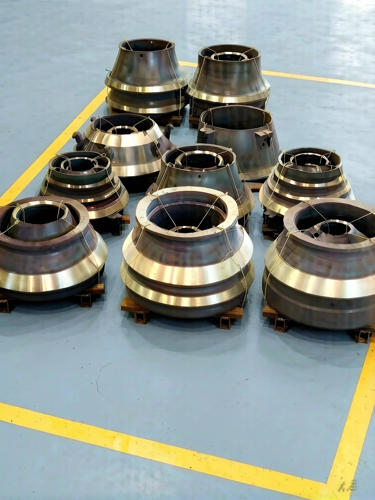
Heavy-duty manganese steel crusher mantles and concaves in manufacturing warehouse
A batch of precision-machined crusher liners ready for final inspection and export.

Reliability in High-Volume Component Supply

At SinoMachine, we bridge the gap between complex engineering requirements and large-scale industrial execution. Our facility specializes in the production of high-manganese steel wear liners, ensuring that global mining operations maintain peak uptime.

Why Partner with Our Industrial Group?

30 Years of Export Expertise: We understand the logistical and technical nuances of international heavy-duty shipments.
IP Integrity & Professional Ethics: Operating under strict NDAs, we act as a transparent and reliable OEM partner for world-class equipment brands.
Integrated Quality Control: From the initial sand casting process to final precision machining, every stage is documented to meet ISO standards.

Production Versatility

Our core strength lies in our ability to handle high-tonnage casting projects. We don’t just supply parts; we provide a stable supply chain anchor. Our current production includes:

Crusher Internals: Mantles, concaves, and jaw plates.
Material Grades: Proprietary Mn13Cr2 through Mn22Cr2 alloys.
Finish: Precision-ground mating surfaces for seamless on-site installation.

Strategic “Co-opetition”

We believe in high-value partnerships. By focusing on performance parity and supply chain reliability, we help our partners navigate market fluctuations without compromising on component quality.

Filed Under: Crusher Wear Parts

October 28, 2025 By Coffy Leave a Comment

Dross Pan Cover: Oxygen Barrier, Not Insulation

Dross Pan Cover: Why It Is an Oxygen Barrier, Not an Insulation Blanket

Ask anyone what a lid does to a hot container and the answer is immediate: it traps heat and slows cooling. That everyday thermal logic fails completely on freshly skimmed aluminium dross — but not for the reason usually given. A dross pan cover does not speed up cooling by “trapping heat in and starving the fire.” It works because hot dross is not a passive heat mass at all — it is a self-heating one, and the cover stops the heat source rather than improving heat extraction.

Key figures
  • Hot dross is skimmed at roughly 680–780 °C — well above the point where metallic aluminium self-heats in air
  • Open pan, uncontrolled: cooling to a safe temperature can take up to 12 hours. Covered with inert gas: well under 4 hours
  • 60–85% of the cooling duty is done by the pan body acting as a heat sink — not by the cover
  • Below about 400 °C, oxidation and aluminothermic reaction stop and metal is no longer lost

1Why the Intuition Breaks Down

Hot water in a covered pot cools more slowly. Nothing about that changes here — a cover does suppress surface convection, and in a purely passive system it would slow cooling down. What breaks the analogy is that hot dross is not passive.

Freshly skimmed white dross leaves the melting or holding furnace at roughly 680–780 °C — a temperature operators read by colour, deep red when too cold and bright yellow-white when too hot. It is a heterogeneous mix of free metallic aluminium droplets, alumina, aluminium nitride and minor salt flux residues. At that temperature, metallic aluminium exposed to air undergoes a self-sustaining exothermic oxidation, widely called thermiting or dross burning:

4Al + 3O2 → 2Al2O3 + heat

This is the point most explanations miss. In an open pan, the dross is not simply losing heat to its surroundings — it is continuously generating new heat for as long as oxygen keeps arriving. Radiation and natural convection are partly offset by that internal heat source. The smoke and fume above an open pan are fine alumina particulates from aluminium vapour and surface combustion, and they are visible evidence of metal being destroyed in real time.

The reaction self-feeds until one of two things happens: the dross temperature falls below roughly 400 °C, at which point oxidation and the aluminothermic phenomenon stop and metal is no longer lost — or the oxygen supply is cut off. A cover addresses the second route.

2What a Cover Actually Does — and What It Does Not

Here is where a lot of casthouse folklore goes wrong, and it is worth being precise because the difference has real commercial consequences.

A cover dropped onto a pan is not a sealed vessel. Air continues to infiltrate through the gap between cover and pan rim, through the aluminium drain holes in the base of a press dross pan (or the ventilation openings in a skim pan base), and around any lifting point. Oxygen trapped in the headspace is consumed within seconds, but it is then replenished. A cover on its own slows oxidation at the exposed surface; it does not reliably extinguish it.

The industrial solution — the Alcan dross cooler design, patented in the early 1990s and still in service at primary casthouses including Ma’aden’s ingot, billet and slab lines — uses three elements together:

  • A compartmentalised pan sized as a heat sink — the patent specifies a pan-to-dross weight ratio of at least 1:1, preferably 1.5:1 to 2:1
  • A hood or cover forming a substantially closed cavity around the filled pan, sealed at the base by a sand bed, refractory wool gasket or machined seat
  • Inert gas injection through a valve in the hood — preferably argon, because nitrogen reacts with molten aluminium and is therefore not recommended for aluminium dross — maintaining positive pressure so air cannot infiltrate

It is the gas that does the oxygen displacement, and it is the positive pressure that keeps air out. The cover’s job is to make that gas volume small enough to be economically purged and held.

Where the heat actually goes

The second half of the correction matters just as much. In the Alcan design, 60–85% of the cooling is done by heat exchange with the pan itself — the pan body absorbs the heat the dross releases. The patent is explicit on the geometry this requires: no dross more than 0.5 m from the nearest pan surface, and a pan surface area exposed to dross of at least 5.0 m², preferably 9.0 m², per cubic metre of pan capacity.

So the correct statement is a two-part one: the pan body removes the heat; the cover stops more heat being made. Remove the internal heat source and the sensible heat remaining in the dross dissipates through the pan walls and cover by conduction and radiation — and the net effect is a dramatically shorter cooling cycle. This is also why pan mass is not a cost to be engineered out. It is the heat sink.

3The Numbers Worth Quoting

Cooling-time claims circulate widely in this industry and most of them are unsourced. Here are two figures that are not:

  • Open pan, uncontrolled: cooling to a safe, non-reactive temperature is generally completed within a maximum period of twelve hours, with the actual period depending on the metal content of the dross and its major alloying constituents
  • Covered with inert gas: one-tonne lots of partially incandescent (yellow heat) dross were cooled safely to below 400 °C in well under four hours

Industry literature describes pans being held under the inert atmosphere for roughly 4–7 hours until the temperature drops below 400 °C — a figure carried in AlCircle’s Aluminium Dross Processing: A Global Review, whose technology-evolution section draws on David J. Roth’s industry paper History & Future of Dross Processing (Light Metals 2015). Whatever the exact figure at your plant, the shape of the comparison is consistent and large: a covered, oxygen-displaced pan reaches a safe temperature in a fraction of the time an open pan needs.

On quoting a percentage. You will see “covers cut cooling time by 50%” stated as fact in supplier literature. We have not been able to trace that figure to any published test data, and we do not use it. Actual results depend on dross metal content, alloy, pan mass ratio, fill level and ambient conditions. If you want a number for your casthouse, it has to come from a trial on your dross — and we would rather help you run one than hand you a figure we cannot stand behind.

4Where a Cover Fits — and Where It Does Not

The mechanism only produces a benefit while the dross is still hot and reactive. Three limits are worth stating plainly:

  • Cold dross — no benefit. Once dross has fully cooled and oxidation has stopped, a cover behaves like any conventional lid: it slows heat loss. Covering cold dross achieves nothing beyond dust containment.
  • White dross — largest benefit. White (primary) dross typically contains roughly 15–80% metallic aluminium. There is a lot of metal to lose, so stopping thermiting pays.
  • Black dross — limited benefit. Black (secondary) dross runs roughly 2–20% metallic aluminium with high salt and oxide content. There is far less free metal to oxidise, so the recovery gain from oxygen exclusion is correspondingly smaller.

5Covers and Dross Presses — Different Stages, Not Alternatives

In most casthouses we supply, there is no lid on the pan at all — and that is a perfectly complete process. The perforated pan set is filled at the furnace, moved by forklift straight into the dross press, and the press head itself closes the pan, arrests thermiting and squeezes the free metal out within minutes. Nothing is left to cool in the open.

A cover belongs to a different stage: where hot dross — or pressed salt cake — is set aside to cool in the pan rather than being processed immediately. In that route there is no press head available to do the closing, and the cover becomes the only barrier between the dross and the air.

So the two are neither competing alternatives nor a required pair. They sit at different points in the flow:

  • Pressing route — no cover needed. The press head performs the sealing and the cooling. Operations with sufficient press capacity and a short furnace-to-press distance may never require a lid.
  • Staged cooling route — cover applies. Where pans are parked to cool before further handling, whether hot dross or pressed salt cake, a cover is used to close the oxidation window that would otherwise stay open.

Where a cover is used for post-press salt cake, it serves the same duty as our aluminium dross cooling pan — moving the material quickly through the reactive temperature band.

6Safety: A Cover Must Never Fully Seal

Hot aluminium dross is not merely hot material — it is a regulated hazardous residue. In transport it is classified UN 3170, Class 4.3, placarded DANGEROUS WHEN WET, and it is listed by name in the IMSBC Code (Group B). Under Chinese regulation, aluminium dross and secondary aluminium dross are listed hazardous wastes — codes 321-024-48 / 321-026-48, hazard characteristic R (reactivity) — classified under GB 5085.5 reactivity testing for exactly the reason below.

That hazard is water reactivity. Contact with moisture releases three gases at once, not one:

  • Ammonia (NH3) from aluminium nitride — AlN + 3H2O → Al(OH)3 + NH3. Toxic and irritant.
  • Hydrogen (H2) from finely divided metallic aluminium — 2Al + 6H2O → 2Al(OH)3 + 3H2. Flammable and explosive.
  • Methane (CH4) from aluminium carbide — Al4C3 + 12H2O → 4Al(OH)3 + 3CH4. Flammable and explosive.

Testing on dross samples from six large secondary aluminium plants recorded ammonia release of 43.1–68.8 mg/kg and hydrogen evolution of 0.5–1.5 L/(kg·h) — every sample reacted. Both the IMSBC Code and ERG Guide 138 therefore prohibit water as an extinguishing medium: dry sand, dry powder or Class D media only.

The practical consequence is the one that matters here: a gas-generating material of this kind must not be sealed into a closed vessel.

The engineering requirement is therefore substantially closed, not hermetically sealed. The reference designs achieve this with sand seals, refractory wool or high-temperature gaskets at the base of the hood — a sand seal additionally avoids the hazards associated with older water-seal designs — and the cavity is held at slight positive pressure with inert gas. Degassing paths must be preserved, and covers should be specified with that requirement stated explicitly on the drawing.

7What to Specify When Ordering a Cover

Covers are manufactured against the pan they sit on. There is no catalogue item, because the sealing geometry is defined by the pan rim. To get an accurate quotation and a correct engineering recommendation, include:

  1. Pan drawings or dimensional sketch — rim profile, overall dimensions, aluminium drain hole layout
  2. Whether inert gas will be injected, and which gas — this determines the sealing specification and whether a gas port is required
  3. Dross type and temperature at filling — white, black or mixed; expected metal content
  4. Handling method — forklift, overhead crane, or dedicated lifting frame; lifting lug positions required
  5. Material grade required, or the operating conditions and observed wear pattern if you want a recommendation
  6. Quantity, and whether this is a one-off replacement or a fleet-wide programme

And hold the supplier to the same standard in return: material grade named, tare weight, lifting lug rated capacity, expected service life and warranty terms with the conditions they assume, production drawings issued for approval before manufacture, tiered pricing, and delivered pricing quoted separately from ex-works.

In One Sentence

A dross pan cover is not an insulation blanket. It is an oxygen barrier that stops hot dross generating its own heat, working alongside a pan body heavy enough to carry the heat away. The confusion casthouse engineers feel on first hearing it — how can a lid make hot material cool faster? — resolves once you stop thinking about heat extraction and start thinking about the heat source.

Further reading: key design features of SMI skim pans, slag bins and sow moulds — including pan mass, chamber geometry and rim reinforcement.

Next step

Send SMI your pan drawings for a cover review and quotation

Filed Under: Dross Management

October 13, 2025 By Coffy Leave a Comment

Aluminum Dross Press & Dross Processing: Equipment, Recovery and Applications

Aluminum Dross Press & Dross Processing

Sino Machine Industries (SMI) supplies aluminum dross press systems and related casthouse equipment for primary aluminum smelters, secondary aluminum producers, aluminum casting facilities and metal recycling operations. Since 1996, SMI has served the aluminum and metal recycling industries with equipment and customized industrial products designed around specific operating requirements.

Our product scope includes aluminum dross presses, dross press heads, dross pans, cooling pans and associated cast-house components. Depending on the project, equipment may be supplied individually, as matched component sets, or as part of a broader dross management and metal recovery solution.

Aluminum Dross Processing: Why Equipment Selection Matters

Aluminum dross is generated during melting, holding, alloying and other molten-metal operations. Its composition varies with furnace type, alloy, operating conditions, flux use, handling practices and the time elapsed after skimming.

Depending on its origin and condition, dross may contain recoverable metallic aluminum, aluminum oxides, flux salts and other constituents. The proportion of recoverable metal is not constant across all dross streams.

Effective dross management therefore requires more than selecting a press with a particular rated capacity. The process must account for how dross is generated, transferred, pressed, cooled, transported and subsequently processed.

A properly specified hot aluminum dross press can help recover free metallic aluminum at the casthouse before the material undergoes further oxidation. Its actual performance depends on the dross characteristics, operating procedures, press configuration, cooling arrangement and measurement method.

How an Aluminum Dross Press Works

An aluminum dross press is designed to separate recoverable metallic aluminum from freshly skimmed hot dross through controlled mechanical pressing.

A typical operating sequence includes the following stages:

1. Dross skimming and collection

Dross is removed from the furnace and collected in a suitable dross pan. Prompt and controlled transfer is important because prolonged exposure to high temperatures and air can increase oxidation and reduce the amount of recoverable metallic aluminum.

2. Positioning and pressing

The loaded pan is positioned in the press according to the equipment design. The press head applies controlled hydraulic force to compact the hot dross and promote the discharge of liquid aluminum through the designed drainage passages.

3. Metal collection

The separated metallic aluminum is collected for appropriate return to the melting process or other suitable handling, subject to alloy quality and plant procedures.

4. Cooling and residue handling

The remaining dross or salt-bearing residue is handled and cooled using a procedure appropriate to its composition and the installation. The subsequent treatment route depends on the material characteristics and applicable safety and environmental requirements.

A dross press is one stage of an overall recovery process. It does not, by itself, eliminate the need for downstream treatment or appropriate management of the remaining residue.

SMI Aluminum Dross Press Systems

SMI offers dross press equipment for different production requirements, including small and medium-sized melting and casting facilities and larger aluminum production operations.

The existing SMI product range includes three model designations:

  • SMI40: A smaller-capacity configuration.
  • SMI60: A medium-capacity configuration.
  • SMI80: A larger-capacity configuration.

The historical SMI product specification lists nominal single-cycle dross capacities of approximately 250–300 kg for SMI40, 450–500 kg for SMI60 and 600–700 kg for SMI80. These figures should be treated as preliminary selection references and verified against the current equipment specification and the customer’s actual dross characteristics.

The appropriate configuration should be determined by considering the quantity of dross generated per cycle, the number of furnaces served, the operating schedule, available handling equipment and the required cycle time.

Customized configurations may be considered where the standard arrangement does not match the installation requirements.

Dross Press Heads and Dross Pan Sets

The press head and dross pan are closely related components in a hot dross pressing system. Their geometry, clearances, drainage arrangements and thermal behavior affect the operation of the equipment.

SMI supplies dross press heads and dross pan sets in configurations selected according to the press design and customer requirements.

Important considerations include:

  • Existing press frame and head dimensions.
  • Pan geometry, capacity and drainage-hole arrangement.
  • Material selection and resistance to thermal cycling.
  • Forklift pockets, lifting points and handling clearances.
  • Compatibility between the press head, pan and operating cycle.
  • Cooling arrangements and the condition of existing equipment.

Where replacement components are required for an existing installation, drawings, dimensional sketches, photographs and equipment identification details help establish compatibility before production.

For third-party equipment, suitability must be confirmed through an engineering review rather than assumed from nominal dimensions alone.

Dross Cooling and Downstream Processing

Hot dross pressing and downstream dross recycling perform different functions and should be evaluated separately.

After pressing, the remaining material may still contain metallic aluminum trapped within an oxide-rich matrix. Depending on the dross type and the recovery objective, additional processing may include controlled cooling, crushing, screening and separation.

A typical downstream arrangement may include:

  • Dross cooling equipment.
  • A suitable crushing or milling stage.
  • Screening and classification equipment.
  • Collection and handling systems for separated fractions.
  • Dust control and residue management equipment, where required.

Not every plant needs the same configuration. The appropriate process depends on whether the feed is primary or secondary dross, whether flux salts are present, the residual metal content, the intended recovery route and local environmental requirements.

Salt-bearing residues from secondary aluminum operations may require dedicated treatment. Mechanical pressing should not be regarded as a complete salt-slag treatment process.

Aluminum Dross Management, Safety and Environmental Considerations

Modern dross management involves more than maximizing the quantity of recovered metal. Material handling, cooling, storage, transportation, worker protection and the management of processing residues are also important.

The International Aluminium Institute’s 2026 Sustainable Aluminium Dross Management Guidance emphasizes an integrated approach to dross generation, handling, cooling, processing, recovery, safety and residue utilization.

For equipment selection and plant planning, the following principles are relevant:

  • Establish a defined procedure for hot-dross handling and transfer.
  • Select cooling and processing methods appropriate to the material.
  • Assess dust, heat, moving machinery and other workplace hazards.
  • Provide suitable guarding, interlocks and operating controls for the specified installation.
  • Evaluate residue composition and the applicable treatment or disposal requirements.
  • Review local environmental, transport and waste regulations before determining the final processing route.

Certain aluminum dross and salt-bearing residues can release hazardous or flammable gases when exposed to unsuitable treatment conditions, including uncontrolled contact with water. Residue treatment must therefore be based on its actual composition and an appropriate process-safety assessment.

Environmental performance and regulatory compliance depend on the complete operating system, not on the press alone.

Applications

SMI dross press equipment and related casthouse products may be relevant to:

  • Primary aluminum smelters.
  • Secondary aluminum smelters and remelting plants.
  • Aluminum billet, bar and rod production facilities.
  • Aluminum casting and foundry operations.
  • Aluminum recycling and metal recovery plants.
  • Non-ferrous metal processing facilities, subject to material and process compatibility.

Equipment selection should reflect the specific production process rather than the industry label alone.

Selecting the Right Dross Press Configuration

A useful technical assessment begins with the customer’s existing process and operating requirements.

To help evaluate a new system or replacement equipment, please provide as much of the following information as available:

  • Furnace type, number of furnaces and production process.
  • Dross type and approximate quantity generated per shift.
  • Typical dross weight per pan or pressing cycle.
  • Existing press model, press-head dimensions and pan drawings.
  • Available floor space and material-handling arrangements.
  • Hydraulic, electrical and cooling-water requirements, where applicable.
  • Required automation level and intended scope of supply.
  • Applicable inspection, documentation and safety requirements.

These details help establish a suitable configuration, identify compatibility issues and determine whether a complete press system or selected replacement components would better meet the requirement.

SMI: Dross Press Equipment and Customized Industrial Components

Sino Machine Industries supplies aluminum dross press equipment and related industrial components for aluminum production and recycling applications. Our scope can include complete equipment packages, matched press-head and dross-pan sets, cooling pans and customized cast components, depending on the project.

We work from the customer’s drawings, specifications and operating requirements to evaluate the appropriate product configuration. Equipment scope, technical parameters, inspection arrangements and delivery requirements are established for each individual project.

For related information, please explore our aluminum dross press systems, dross press heads and dross pan sets, aluminum dross cooling pans, casthouse skimming tools and aluminum dross recycling equipment.

Request Technical Information or a Quotation

If you are planning a new dross press installation, replacing existing components or reviewing your current dross recovery process, SMI welcomes your enquiry.

Please send your equipment drawings, current specifications, approximate dross volume and intended scope of supply to inquiry@sinomachine.org.

Our team can review the available information and advise on a suitable equipment or component configuration for your application.

Filed Under: Aluminium Industry Equipment, Dross Management, Dross Press & Dross Processing, Metal Recycling, Recycling, Recycling, New energy and Environmental protection

  • Page 1
  • Page 2
  • Page 3
  • Interim pages omitted …
  • Page 25
  • Go to Next Page »

Primary Sidebar

  • Home
  • About Us
  • Industries Served
    • SMI Products Overview
      • SMI Special Steel Products 01
      • SMI Special Steel Products 02
      • SMI Metal Recycling
      • NDT (Non Destructive Testing) service
  • Capabilities
    • Aluminum Industry
      • Aluminum Dross Press
      • Aluminum Dross Cooling Pan
      • Alloy Steel Sow Mold
      • Aluminum Dross Skim Blades and Skim Tools
      • Aluminum Furnace Skimming Tool or Skim blades used for Stirring and Mixing
      • Dross Press & Dross Processing
      • Application of Intelligent Ladle Slag Scraper (Skimming Tools) in steel mills and aluminum mills
      • Transmission Parts
      • The correct combination of the press head and the dross pan
      • 7-9kgs Small Standard Ingot Molds | Moldes de lingotes estándar pequeños de 7-9kgs
      • Comparison between Sow Molds and Ingot Molds
      • Aluminum Dross Transport Equipment
      • Aluminum Dross Recycling Systems
      • Aluminum, Magnesium, Brass, Bronze, Lead, Zinc Ingot Molds
      • Anode steel claw (Electrolytic claw) | Garra de acero del ánodo (garra electrolítica)
      • Anode Steel Yoke
  • eNews
  • Contact Us

Footer

Customized Products & Services

Professional Aluminum & Magnesium plant equipment supplier from China.
Up to 4,000 metric tons of mechanical products annually.
More than 30 years’ manufacturing and export experience.
Serving Global Aluminum & Magnesium smelters and metal recycling industry since 1996.

Recent Products & Services

  • High-Performance Aluminum Ingot Molds: The Complete Selection Guide
  • Casting vs Forging vs Machining: Choosing by Wear Mechanism
  • Ingot Mold Failure Modes: Causes, Prevention & Lifespan Tips
  • Global OEM Supply Chain: Heavy-Duty Crusher Wear Parts Manufacturing
  • Dross Pan Cover: Oxygen Barrier, Not Insulation

Found favorite parts & services

Sino Machine Industries — Heavy Industry Supplier with 30 Years of Manufacturing Expertise in Aluminium, Crushing & Transmission Parts. Serving primary smelters, recycling plants and OEM clients across 30+ countries. Get a free quote: [Inquiry@sinomachine.org]
  • Home
  • Privacy Policy
  • Terms of Use
  • Download Center
  • Site Map
  • Contact Us

Copyright © 2026 Sino Machine Industries (SMI) Serving Global Machinery Markets Since 1996