• Skip to main content
  • Skip to primary sidebar
  • Skip to footer

Sino Machine Industries

  • Home
  • About Us
  • Industries Served
    • SMI Products Overview
      • SMI Special Steel Products 01
      • SMI Special Steel Products 02
      • SMI Metal Recycling
      • NDT (Non Destructive Testing) service
  • Capabilities
    • Aluminum Industry
      • Aluminum Dross Press
      • Aluminum Dross Cooling Pan
      • Alloy Steel Sow Mold
      • Aluminum Dross Skim Blades and Skim Tools
      • Aluminum Furnace Skimming Tool or Skim blades used for Stirring and Mixing
      • Dross Press & Dross Processing
      • Application of Intelligent Ladle Slag Scraper (Skimming Tools) in steel mills and aluminum mills
      • Transmission Parts
      • The correct combination of the press head and the dross pan
      • 7-9kgs Small Standard Ingot Molds | Moldes de lingotes estándar pequeños de 7-9kgs
      • Comparison between Sow Molds and Ingot Molds
      • Aluminum Dross Transport Equipment
      • Aluminum Dross Recycling Systems
      • Aluminum, Magnesium, Brass, Bronze, Lead, Zinc Ingot Molds
      • Anode steel claw (Electrolytic claw) | Garra de acero del ánodo (garra electrolítica)
      • Anode Steel Yoke
  • eNews
  • Contact Us

Industries We Serve

October 11, 2019 By Coffy Leave a Comment

Sow Moulds and DCU (Dross Compression Unit)

DCU Dross Compression Unit — Aluminum Dross Press in Operation
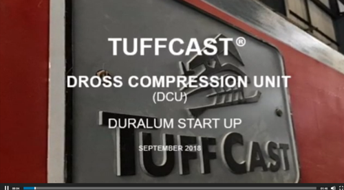
DCU Dross Compression Unit for Aluminum Dross Press
DCU (Dross Compression Unit)

DCU — Dross Compression Unit for Aluminum Dross Recovery

A DCU (Dross Compression Unit) is an aluminum industry term for what is more commonly referred to as an aluminum dross press — a hydraulic compression system designed to recover free metal from hot aluminum dross at the point of generation. The terminology differs across markets and operations; the engineering objective is the same: compress hot dross rapidly under controlled hydraulic force, arrest oxidation through integrated cooling, and produce a dense aluminum block with the maximum recoverable metal content.

SMI designs, manufactures and supplies DCU systems as part of its complete aluminum dross press equipment range. SMI DCU systems are the product of over 30 years of casthouse operational experience and continuous engineering development — incorporating design improvements that directly address the geometric and thermal limitations of earlier dross compression unit designs in the industry.

Early dross compression unit designs relied on pan geometries that prioritised volume over seal integrity — a trade-off that limited recovery performance under sustained operational pressure. SMI’s DCU development addressed these geometric limitations directly: tighter mating tolerances between press head and dross pan, improved thermal seal design, and material formulations engineered specifically for the thermiting conditions of hot dross service. The result is measurably better metal recovery and longer component service life under continuous casthouse operation.


SMI Dross Compression Unit — In Operation

The following video demonstrates an SMI DCU installation in active casthouse service. This footage shows an early production configuration — current SMI DCU systems incorporate significant design and material improvements over the configuration shown, reflecting ongoing engineering development based on operational feedback from casthouse installations worldwide.

The video illustrates the core DCU operating cycle: dross pan positioning, hydraulic head descent, compression under controlled pressure, forced cooling activation, and head retraction. The automated cycle requires no manual intervention during pressing, reducing operator exposure to radiant heat and fume while eliminating the skill variability associated with manual dross handling.


DCU System Design — Key Engineering Principles

Press Head and Dross Pan — The Matched Set

The performance of any DCU system is determined primarily by the quality of the match between the press head (cooling head) and the dross pan. The two components must be designed together — the press head profile must seat correctly against the dross pan walls to maintain an effective thermal seal under hydraulic pressure and transfer heat efficiently through the cooling circuit. SMI designs and supplies press heads and dross pans as matched sets for this reason.

Proprietary Material Formulation

SMI press heads and dross pans are manufactured from a proprietary material formulation developed in-house — engineered for thermal shock resistance and dimensional stability under repeated high-temperature cycling. This formulation is the same specification used across SMI’s full range of casthouse consumables, with a 30-year operational record in aluminum casthouses across multiple continents.

Compatibility Across All Dross Types

SMI DCU systems are configured and validated for the full range of industrially relevant dross types — dry, wet, black, white, salt and rotary furnace slag. Each dross type behaves differently under compression; SMI application engineers confirm the correct press head geometry, cooling configuration and dross pan specification for each installation’s specific dross characteristics before order placement.

Upgrade and Retrofit

For operations with existing DCU or dross press installations from any manufacturer, SMI provides upgrade and retrofit supply — replacement press heads, dross pan sets and system improvements — without requiring full system replacement. Where the press frame is serviceable, targeted component upgrades can deliver significant improvements in recovery performance. All third-party press frame adaptations are subject to engineering review before supply confirmation.


Sow Moulds — Overview

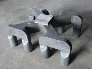
SMI also supplies alloy steel sow moulds for aluminum casthouses. Sow moulds are reusable cast steel moulds used to form aluminium ingots and cast molten metal from furnaces and transfer launders. SMI sow moulds are manufactured from proprietary alloy steel formulations engineered for thermal shock resistance and long service life in continuous casthouse operation.

Standard and low-profile designs are available in multiple sizes, with options for air-cooled applications, sow feet, lugs and hooks, fork channels, and application-specific material chemistries. Custom configurations — including logo casting and dimensional modifications — are available on request. For the full sow mould product range and specifications, see the SMI Alloy Steel Sow Mould and Dross Skim Pans and Sow Moulds pages.


Related Products — Complete Dross Management from SMI

  • Aluminum Dross Press Systems — SMI40, SMI60, SMI80 and custom configurations
  • Dross Press Cooling Head — cooled and uncooled variants, all geometries
  • Dross Press Equipment Overview — system configurations and upgrade options
  • Dross Skim Pans and Sow Moulds — matched pan-and-head sets
  • Aluminum Dross Cooling Pan — rapid salt cake cooling post-press
  • Aluminum Dross Recycling Systems — full downstream processing line
  • Alloy Steel Sow Moulds
  • Ingot Molds, Sow Moulds and Dross Pans for Aluminum Scrap Recycling

Request a Quotation or Technical Consultation

To discuss DCU system requirements, press head and dross pan configuration, or sow mould specifications, please contact SMI’s application engineering team with the following information:

  • Operation type: primary smelter / secondary smelter / recycling plant
  • Furnace type and dross generation rate
  • Dross type: dry / wet / black / white / salt / rotary furnace slag
  • Existing equipment: press frame, pan set, cooling system if applicable
  • Sow mould requirements: standard / low-profile / custom dimensions
Contact SMI — DCU and Sow Mould Enquiry →

Filed Under: Dross Management Tagged With: aluminium casting, DCU, dross compression unit, Dross Press, Sow Mold

April 9, 2019 By Sen Liang Leave a Comment

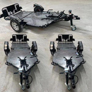
Trailer Jack

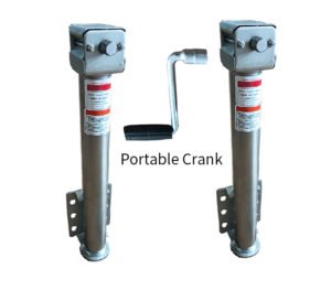
Trailer Jack

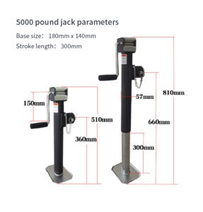
5000 pound jack parameters
Portable Crank for trailer jack
Customized Trailer Jack

SMI specializes in customizing trailer accessories since 1996, including Weight Distribution & Sway Control System, Flat_bottom Jacks, and Wheeled Jacks, etc. It is very popular in the trailer accessories market in the United States and Australia.

Filed Under: Design, Research & Development, Transmission Parts, Truck & Trailer Parts Tagged With: Trailer Jack

March 7, 2019 By Sen Liang Leave a Comment

Anode steel claw (Electrolytic claw) | Garra de acero del ánodo (garra electrolítica)

Cast Steel Anode Yoke — Electrolytic Aluminium Production Consumables

The cast steel anode yoke — also referred to as anode steel claw, electrolytic claw, electrolysis claw or anode yoke bracket — is a critical consumable in the electrolytic aluminium production process. It forms the structural and electrical connection between the aluminium guide rod above and the anode carbon block below, transmitting both the mechanical load and the high-amperage direct current required for the electrolytic reduction of aluminium oxide to aluminium metal.

SMI has been supplying cast steel anode yokes to primary aluminium smelters for over 30 years. All configurations are produced to customer specification — covering claw geometry, dimensional drawing, steel grade and electrical conductivity requirements.

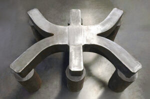
SMI cast steel anode yoke six-claw configuration top view new production unit — arc profile claw arms and central cross body low carbon steel Q235 rare earth refined to customer cell specification
Cast steel anode yoke six-claw configuration — new production unit showing arc profile claw arms and central connection body, manufactured to customer dimensional drawing
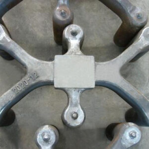
SMI cast steel anode yoke six-claw unit top view showing cylindrical claw end nodes and central square connection plate — in electrolytic aluminium cell service
Cast steel anode yoke in service — six-claw configuration showing cylindrical claw end nodes and central connection plate, primary aluminium electrolytic cell application
Cast steel anode yoke eight-claw single unit three-quarter view showing full claw arrangement cylindrical claw end nodes and central connection block — low carbon steel Q235 rare earth refined for high-amperage electrolytic aluminium cells
Cast steel anode yoke eight-claw configuration — single unit three-quarter view showing full claw arrangement and cylindrical end nodes, for very high-amperage modern reduction cells

Role of the Anode Yoke in Electrolytic Aluminium Production

In a Hall-Héroult electrolytic cell, the anode assembly consists of an aluminium guide rod connected via the cast steel yoke to a prebaked anode carbon block. The yoke serves three simultaneous functions:

  • Mechanical support — carrying the weight of the anode carbon block suspended in the electrolytic bath
  • Electrical conduction — transmitting high-amperage direct current from the aluminium guide rod through the steel yoke into the carbon block
  • Thermal resistance — withstanding the high-temperature environment of the electrolytic cell during the anode service cycle

The anode carbon block is consumed progressively during electrolysis — typically requiring anode assembly adjustment every 15 to 18 days as the carbon block reduces in height. When the carbon block is consumed to the minimum serviceable dimension, the complete anode assembly is removed and replaced. The used yoke and aluminium guide rod are then returned to the anode assembly workshop for cleaning, inspection and recycling.


Anode Yoke Service Cycle and Recycling

In-Service Cycle

A cast steel anode yoke and its aluminium guide rod typically complete one full service cycle of approximately one month in the electrolysis workshop before removal. During this period, aluminium slag and electrolyte — primarily cryolite (Na₃AlF₆) and aluminium fluoride — accumulate on the yoke surface and in the joints between the steel claw and the carbon block.

Electrolyte and Slag Removal

After removal from the cell, the used anode assembly is transferred to the anode assembly workshop for processing. Aluminium slag and electrolyte deposits on the guide rod and yoke surface are mechanically removed before the components can be recycled or the yoke returned to service.

Phosphorus Iron Ring Removal

During carbon block casting, a phosphorus iron ring is cast around each steel claw to provide the mechanical and electrical interface between the steel yoke and the carbon anode. After carbon block consumption, this phosphorus iron ring remains on the steel claw and must be pressed off before the yoke can be recycled. The removal process uses hydraulic pressing equipment to apply the controlled force required to separate the iron ring from the steel claw without damaging the yoke geometry.

Shot Blast Cleaning and Recycling

Following electrolyte removal and phosphorus iron ring pressing, the steel yoke is shot blast cleaned to remove residual deposits and surface contamination. Cleaned yokes that meet dimensional and structural inspection criteria are returned to the production cycle for reassembly with a new aluminium guide rod and carbon block.


Manufacturing Process

Melting and Refining

SMI produces cast steel anode yokes using electric arc furnace and medium frequency induction furnace melting, with rare earth element additions during the refining stage. Rare earth refining serves two specific functions in anode yoke production:

  • Gas content control — rare earth additions promote the removal of dissolved gases (hydrogen, nitrogen, oxygen) from the molten steel, reducing porosity in the solidified casting and improving the density and structural integrity of the finished yoke
  • Electrical conductivity assurance — controlled steel chemistry achieved through rare earth refining ensures the finished yoke meets the electrical conductivity specification required for efficient current transmission through the anode assembly. Low carbon steel Q235 has inherently good electrical conductivity relative to higher-alloy grades — rare earth refining preserves and optimises this property by minimising non-metallic inclusions and dissolved gas content

Casting and Dimensional Control

Anode yoke casting requires accurate control of claw geometry — the dimensional relationship between the steel claws determines the alignment of the carbon block in the electrolytic cell and the uniformity of current distribution across the anode face. Pattern equipment and casting practice are maintained to the dimensional tolerances specified in the customer’s drawing.

Heat Treatment and Inspection

Finished castings are heat treated to the specified mechanical property requirements and subjected to dimensional inspection, visual inspection and hardness verification before despatch. Material certification covering chemical composition and mechanical properties is supplied as standard.


Technical Specifications

Parameter Specification
Material Low carbon steel Q235 or Q235B — equivalent to BS3100 Grade A1, AS 2074-2003 Grade C2, AISI 1010 / 1008 / 1006
Melting process Electric arc furnace and medium frequency induction furnace
Refining Rare earth addition — gas content control and electrical conductivity optimisation
Melt range 1494°C – 1515°C
Size According to customer’s requirements
Surface finish Ra 12.5 to Ra 25 — or according to customer’s requirements
Applicable standards AISI, ASTM, DIN, GB, BS and equivalent
Anode replacement cycle Typically every 15–18 days per cell position
Yoke service life Approximately one month per cycle before removal and recycling
Quality documentation Chemical composition certificate, mechanical property report, dimensional inspection report

Configurations Available

Configuration Description Typical Application
Parallel three-claw Three claws in parallel planar arrangement Standard medium-capacity electrolytic cells
Four-claw Four claws in planar arrangement Higher-capacity cells requiring greater current distribution
Three-dimensional four-claw Four claws in three-dimensional spatial arrangement Large-format cells requiring optimised current distribution
Six-claw Six claws for high-capacity anode assemblies High-amperage large-format electrolytic cells
Eight-claw Eight claws for maximum current distribution Very high-amperage modern reduction cells
Double yoke Twin yoke configuration for double anode assemblies Double anode cell configurations
Custom Any configuration to customer drawing New cell designs and retrofit requirements

Global Supply

SMI cast steel anode yokes are in active service at primary aluminium smelters across the Middle East, Europe, India, North America and Asia-Pacific, including multiple operations within the world’s highest-output primary aluminium production groups. All supply relationships are subject to confidentiality agreements. Reference accounts are available to qualified buyers under appropriate confidentiality terms.


بالعربية — قيود الأنود الفولاذية المصبوبة لإنتاج الألومنيوم الإلكتروليتي

قيد الأنود الفولاذي المصبوب — المعروف أيضاً بمخلب الأنود الفولاذي أو مخلب التحليل الكهربائي — هو مستهلك أساسي في عملية إنتاج الألومنيوم الإلكتروليتي. يربط قضيب توجيه الألومنيوم العلوي بكتلة الكربون الأنودية السفلية، وينقل التيار المستمر عالي الأمبير اللازم لعملية اختزال أكسيد الألومنيوم إلكتروليتياً. المادة: فولاذ منخفض الكربون Q235 مع إضافات عناصر الأرض النادرة. التكوينات المتاحة: ثلاثة مخالب متوازية، أربعة مخالب، أربعة مخالب ثلاثية الأبعاد، ستة مخالب، ثمانية مخالب، والقيود المزدوجة. جميع المواصفات وفق رسومات العميل. للاستفسار، تواصل مع فريق SMI →


En Español — Yugos de Ánodo de Acero Fundido para Producción de Aluminio Electrolítico

El yugo de ánodo de acero fundido — también denominado garra de acero del ánodo, garra de electrólisis o garra electrolítica — es un consumible esencial en el proceso de producción de aluminio electrolítico. Conecta la varilla guía de aluminio superior con el bloque de carbono anódico inferior, transmitiendo la corriente continua de alta intensidad necesaria para la reducción electrolítica del óxido de aluminio. Material: acero de bajo carbono Q235 con adiciones de tierras raras. Configuraciones disponibles: tres garras paralelas, cuatro garras, cuatro garras tridimensionales, seis garras, ocho garras y yugos dobles. Todas las especificaciones según planos del cliente. Para consultas, contacte al equipo de SMI →


Related Products — SMI Aluminium Industry Equipment

  • Dross Skim Pans and Sow Molds — alloy steel casthouse consumables
  • Alloy Steel Sow Mold — 8630 WCB 9 and SMI & HT anti-thermal shock material
  • Aluminum Dross Press — SMI40, SMI60, SMI80 complete dross press systems
  • Contact SMI — Anode Yoke Enquiry →

Request a Quotation

To enquire about cast steel anode yoke supply, please provide the following at enquiry stage:

  • Cell type and amperage — reduction cell design and operating current
  • Claw configuration — number of claws and spatial arrangement
  • Dimensional drawing or sketch — claw spacing, yoke body dimensions
  • Steel grade and electrical conductivity specification
  • Annual consumption volume — yokes per year per cell line
  • Current supplier and any known quality or service life issues

SMI will respond with a written technical assessment and commercial proposal. Contact SMI — Anode Steel Yoke Enquiry →

Filed Under: Casting Consumables Tagged With: anode assembly, anode steel claw, electrolytic claw, primary smelter

December 24, 2018 By Coffy Leave a Comment

SMI Dross Processing in Aluminum Recycling Operations

Dross Processing in Aluminium Recycling Operations — Pan Design, Press Configuration and Why Results Vary

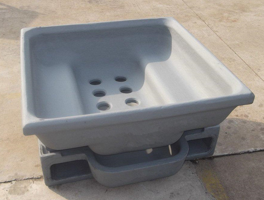
SMI alloy steel dross pan with multi-hole drain configuration and fork channels for aluminium casthouse dross processing
SMI alloy steel dross pan — multi-hole drain configuration with double counter-sink design, fork channels and large pan mass for maximum thermal cooling contact. Manufactured from proprietary alloy steel formulation for thermal shock resistance and long service life in continuous casthouse operation.

SMI has been supplying dross pans and dross press systems to the aluminium industry for over 30 years. Since 2009, Mr. David Roth has been our head consultant, bringing decades of experience in the global aluminium industry to SMI’s equipment design and customer application work.

All of the major players in aluminium melting and casting have purchased SMI quality castings. The observations in this article are drawn from that operational experience — from installations that worked well and from installations that did not, and from understanding precisely why the difference occurred.


The Dross Pan — Where Recovery Begins

The dross pan is not a passive container. Its design directly determines how much metal is recovered in the pressing cycle that follows. The unique characteristics of SMI’s dross pan design allow for a significant degree of cooling contact between the dross and the cast steel — a function of pan mass, geometry and surface area that cannot be replicated by a simple fabricated vessel.

The drain hole configuration is a specific engineering decision, not a standard feature. The number of holes and the double counter-sink design allows for the maximum drain possible without dross sticking in the holes — a failure mode that renders the drain function ineffective and forces operators to intervene manually. The distance between the skim position and the sow mould is also considered carefully in the pan design, to allow large drain volumes without the pans freezing together during the transfer process.

The cooling cycle for correctly specified dross pans is approximately two hours before the material can be rotated out. The large pan mass is critical to achieving this result — it is what drives the thermal extraction that makes the subsequent pressing cycle effective.

Some earlier pan designs in the industry relied on single-hole drain configurations. A single drain point is inherently prone to blockage given the viscosity and oxide content of hot dross — when it blocks, the entire drain function is lost. The single-chamber pan geometry also limits the cooling and plating action achievable during pressing. SMI’s multi-hole, double counter-sink design addresses both failure modes directly.

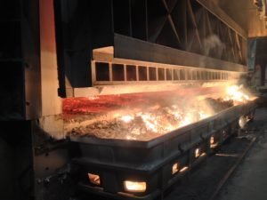
Hot aluminium dross being skimmed from furnace into SMI dross pan — casthouse operation
Hot aluminium dross being skimmed from the furnace into the dross pan — time from skimming to pressing is the critical variable in metal recovery
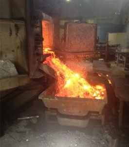
Liquid aluminium visible in freshly skimmed hot dross — immediate pressing required to prevent oxidation loss
Liquid aluminium visible in freshly skimmed hot dross — oxidation begins immediately after skimming
Forklift transfer of loaded SMI dross pan to aluminium dross press — fork channel design accommodates standard casthouse material handling
Forklift transfer of loaded dross pan to the dross press — pan design accommodates standard fork truck specifications for each installation

Press Capacity — The Operational Variable Most Often Underestimated

The most consistent cause of dross press underperformance in the field is not equipment quality — it is insufficient press capacity relative to the dross generation rate of the operation.

The mechanism is straightforward. Hot dross skimmed from the furnace begins oxidising immediately. The cooling and plating action that is the primary benefit of pressing — the conversion of liquid aluminium droplets into a recoverable solid block — requires the dross to reach the press while still at temperature. If a dross pan sits for more than 15 minutes before pressing, this process is already significantly compromised. The dross has cooled, the liquid aluminium has partially oxidised, and the pressing cycle produces a result that does not reflect the capability of the equipment.

When multiple pans queue in front of a single press, the pans at the back of the queue are already cold before they are processed. Operators observe poor results, conclude that pressing is ineffective, and gradually stop using the equipment — not because the press is at fault, but because the system was never configured with adequate capacity for the volume of dross being generated.

The practical implication for system specification is direct: the number of presses required for an operation is determined by the dross generation rate and the 15-minute processing window — not by capital budget alone. An undercapacity installation does not produce partial results; it produces results that appear to confirm that pressing does not work, which is a different and more damaging outcome.


The Pan and Press Head as a Matched System

The most important engineering decision in a dross press installation is the casting design of the pan and the press head as a matched pair. The press head must seat correctly against the pan walls to maintain an effective seal under hydraulic pressure — a poor geometric match allows dross to escape under compression and breaks the thermal contact that drives cooling performance.

SMI designs the pan and press head together, specifically for each customer’s furnace configuration, dross volumes and material handling capabilities — fork truck specifications, transfer distances and pan positioning. The combination of pan design and press head geometry determines the fastest possible cooling rate, the highest achievable drain volume and the most effective plating action for the specific dross type being processed.

The press itself — hydraulics, frame, automation — is in SMI’s view a delivery mechanism for the casting design. A high-quality press delivering poor results is almost always a pan-and-head geometry problem, not a press problem. SMI’s focus is on providing a high-quality, simple, low-maintenance press that fully utilises the recovery capability built into the casting design.


Operational Recommendations

Based on over 30 years of dross press installations across primary smelters, secondary smelters and recycling operations, SMI’s application engineering team consistently observes the following in operations that achieve the best results:

  • Minimise time from skimming to pressing — the 15-minute window is a real operational constraint, not a guideline. Workflow design should prioritise getting hot dross to the press as the first priority after skimming.
  • Size press capacity to dross generation rate — calculate the number of pans generated per shift and confirm that press capacity can process them all within the 15-minute window. If the numbers do not support a single press, two presses is the correct specification.
  • Specify pan and press head as a matched set — do not select the press and the pan independently. The geometric relationship between them is the primary determinant of recovery performance.
  • Maintain the pan-to-head seal — a worn or damaged mating face on either the pan or the head degrades recovery performance continuously. Replacement scheduling should be based on dimensional inspection, not visible failure.
  • Account for dross type — different furnace types and alloy practices produce dross with different characteristics. Pan and head geometry should be confirmed for the specific dross type being processed, not selected from a generic catalogue.

SMI Dross Pan Design — Key Features

Design Feature Function Failure Mode Addressed
Multi-hole drain configuration Maximum drain volume during pressing Single-hole blockage — loss of drain function
Double counter-sink hole design Prevents dross sticking in drain holes Hole blockage requiring manual intervention
Large pan mass Thermal mass drives cooling contact with dross Insufficient cooling — poor plating action
Pan-to-head matched geometry Effective seal under hydraulic pressure Dross escape and thermal seal failure under compression
Furnace-specific dimensioning Correct volume for furnace dross output Undersized or oversized pans relative to dross generation
Fork truck compatibility Safe transfer from furnace to press Handling delays that extend the pre-press window beyond 15 minutes

Related Products

  • Dross Skim Pans and Sow Moulds — matched pan-and-head sets, proprietary alloy steel
  • Dross Press Cooling Head — cooled and uncooled variants, all geometries
  • Aluminum Dross Press — SMI40, SMI60, SMI80 and custom configurations
  • Dross Press Equipment Overview — system configurations and upgrade options
  • Press Head and Dross Pan — matched configuration guide
  • Aluminum Dross Cooling Pan — post-press salt cake and dross cooling unit
  • Aluminum Dross Recycling Systems — complete downstream processing line

Contact SMI — Dross Processing Application Enquiry

To discuss dross pan and press head specification for your operation, or to review an existing installation that is not achieving expected recovery results, please contact SMI’s application engineering team. Please provide your furnace type, dross generation rate per shift, current pan and press configuration, and dross type.

SMI will respond with a written assessment and recommendation. Contact SMI →

Filed Under: Dross Management Tagged With: Aluminum Recycling, dross pan, Dross Press, dross processing, secondary smelter, SMI

March 8, 2018 By Sen Liang Leave a Comment

Cast Iron Alloying Cage

SMI Cast Iron Alloying Cage

Used for magnesium alloying in aluminum cast house furnaces. Mg capacity: 260kg ~ 650 kg
Casting Alloy Cage, Magnesium Alloying Cage For Aluminum Furnace Equipment.

Application:
Using for adding alloy into aluminum cast house furnaces. For example magnesium, manganese, nickel and so on into aluminum furnaces. Attach the cage to a long pole. And the other end can be lifted using a forklift to add the required alloy to the furnace.

Place of Origin: China
Model Number: According to customer’s specifications
Application: Aluminum Industry
Material: Casting Alloy Steel
Capacity available: 260kg ~ 650kg
Got free quote today: inquiry@sinomachine.org

Jaula de aleación de hierro fundido
Se utiliza para la aleación de magnesio en hornos domésticos de fundición de aluminio. Capacidad de Mg: 260 kg ~ 650 kg
Jaula de aleación de fundición, jaula de aleación de magnesio para equipos de hornos de aluminio.

Aplicación:
Se usa para agregar aleación en hornos domésticos de fundición de aluminio. Por ejemplo, magnesio, manganeso, níquel, etc., en hornos de aluminio. Sujeta la jaula a un poste largo. Y el otro extremo se puede levantar con una carretilla elevadora para agregar la aleación requerida al horno.

Aplicación:
Se usa para agregar aleación en hornos domésticos de fundición de aluminio. Por ejemplo, magnesio, manganeso, níquel, etc., en hornos de aluminio. Sujeta la jaula a un poste largo. Y el otro extremo se puede levantar con una carretilla elevadora para agregar la aleación requerida al horno.

Lugar de origen: China
Número de modelo: ¡De acuerdo con las especificaciones del cliente!
Aplicación: Industria del aluminio
Material: fundición de acero aleado
Capacidad disponible: 260 kg ~ 650 kg
Obtuve una cotización gratis hoy: inquiry@sinomachine.org

Filed Under: Furnace Tools & Accessories

January 7, 2018 By Coffy

Daily Design Works- Agriculture gearboxes

Agriculture Gearbox Design and Manufacturing — Rotary Lawn Mower Series

SMI’s engineering team designs and manufactures agricultural gearboxes from initial concept through to finished product — covering 3D CAD design, casting, precision machining and assembly. The rotary lawn mower gearbox series shown on this page represents one area of SMI’s mechanical design and manufacturing capability, with configurations supplied to agricultural equipment manufacturers in Canada and other markets.

All gearbox configurations are developed to customer specification. SMI does not supply standard catalogue products — every configuration is engineered to the specific input/output requirements, mounting geometry and performance specification of the customer’s equipment.

SMI agriculture gearbox 3D CAD sectioned model showing multi-stage gear train, shaft layout and internal assembly — in-house engineering design capability
3D CAD section view of SMI-designed rotary mower gearbox — multi-stage gear train, bearing layout and housing geometry developed in-house before manufacture
SMI agriculture gearbox aluminium alloy housings in production — batch casting showing consistent dimensional quality
Aluminium alloy gearbox housings in production — in-house casting gives SMI direct control over dimensional accuracy and surface finish quality

Design and Manufacturing Capability

In-House CAD Engineering

SMI’s engineering team develops full 3D CAD models of gearbox assemblies before manufacture — covering gear geometry, shaft layout, bearing selection, housing design and assembly clearances. The sectioned CAD model shown above illustrates the multi-stage gear train and internal layout typical of SMI’s rotary mower gearbox designs. In-house design capability means SMI can work from a customer’s functional specification or performance requirement, not just from a finished drawing.

Casting and Housing Manufacture

Gearbox housings are manufactured in-house from aluminium alloy castings — as shown in the production image above. Casting in-house gives SMI direct control over dimensional accuracy, wall thickness consistency and surface finish quality, which are critical to gear alignment and bearing life in the finished assembly.

Precision Machining and Assembly

Machined bores, bearing seats, shaft features and mounting faces are produced to the tolerances required for correct gear mesh and bearing fit. Final assembly and functional verification are carried out before despatch.

SMI 30-40 hp rotary lawn mower gearbox blue configuration - horizontal shaft layout, aluminium housing
30-40 series rotary mower gearbox – orizontal shaft configuration, custom colour and mounting to customer specification
SMI 30-40 hp rotary lawn mower gearbox red horizontal shaft configuration — gear ratio and shaft dimensions to customer specification
30-40 series horizontal shaft configuration in red — shaft layout and mounting pattern customisable to OEM specification
SMI 30-40 hp rotary lawn mower gearbox black vertical output shaft configuration — surface treatment and colour to customer specification
30-40 series vertical shaft configuration in black finish — output shaft orientation and surface treatment customisable to OEM requirement
SMI 30-40 hp rotary lawn mower gearbox right-angle drive tall body configuration — splined output shaft for mower deck applications
30-40 series right-angle drive configuration — splined output shaft and flange mounting for rotary mower deck installations
SMI 30-40 hp rotary lawn mower gearbox compact upright configuration — small form factor for space-constrained installations
30-40 series compact upright configuration — optimised for space-constrained mower deck installations
SMI 50-60 hp rotary lawn mower gearbox heavy-duty circular flange mount configuration — right-angle drive for higher power mowing applications
50-60 series heavy-duty gearbox — circular flange mount and right-angle drive for higher power rotary mower applications
SMI 70-80 hp rotary lawn mower gearbox high-power vertical output shaft with large flange base mount — heavy-duty agricultural mowing equipment
70-80 series high-power gearbox — vertical output shaft with large flange base for heavy-duty rotary mowing applications

Rotary Lawn Mower Gearbox Series

The series shown covers a range of input power classes — from the 30–40 hp range through to the 70–80 hp range — in multiple mounting and shaft configurations. Standard configurations include horizontal shaft, vertical shaft and right-angle drive layouts to suit different mower deck and PTO connection geometries.

Series Power Range Typical Application
30-40 Series 30–40 hp Mid-range rotary mowers — multiple shaft configurations
50-60 Series 50–60 hp Heavy-duty rotary mowers — right-angle drive configuration
70-80 Series 70–80 hp High-power rotary mowers — vertical output shaft configuration

Custom configurations outside this range — different power ratings, gear ratios, shaft dimensions, mounting patterns or housing materials — are available on request. SMI will develop a configuration to the customer’s specific equipment requirements.


Custom and OEM Supply

SMI’s gearbox manufacturing capability is available to agricultural equipment manufacturers requiring:

  • Design from specification — SMI engineers develop the gearbox configuration from the customer’s functional and performance requirements
  • Design from drawing — SMI manufactures to the customer’s existing engineering drawing or CAD model
  • Design improvement — SMI reviews an existing configuration and proposes engineering changes to improve performance, service life or manufacturability
  • OEM supply — finished gearboxes supplied under customer branding and packaging
  • Custom configurations — power rating, gear ratio, shaft layout, housing material, surface finish and colour to customer specification

Request a Consultation

To discuss agricultural gearbox design and supply for your equipment, please provide the following at enquiry stage:

  • Input power — hp or kW
  • Required gear ratio and output shaft speed
  • Shaft configuration — input and output orientation
  • Mounting geometry — bolt pattern, flange or foot mounting
  • Annual volume requirement
  • Existing drawing or specification if available

SMI will respond with a written technical assessment. Contact SMI — Agriculture Gearbox Enquiry →

Filed Under: Gearboxes & Components Tagged With: Agricultural gearbox, farm equipment gearbox, gearbox design, PTO gearbox

  • « Go to Previous Page
  • Page 1
  • Interim pages omitted …
  • Page 11
  • Page 12
  • Page 13
  • Page 14
  • Page 15
  • Interim pages omitted …
  • Page 25
  • Go to Next Page »

Primary Sidebar

  • Home
  • About Us
  • Industries Served
    • SMI Products Overview
      • SMI Special Steel Products 01
      • SMI Special Steel Products 02
      • SMI Metal Recycling
      • NDT (Non Destructive Testing) service
  • Capabilities
    • Aluminum Industry
      • Aluminum Dross Press
      • Aluminum Dross Cooling Pan
      • Alloy Steel Sow Mold
      • Aluminum Dross Skim Blades and Skim Tools
      • Aluminum Furnace Skimming Tool or Skim blades used for Stirring and Mixing
      • Dross Press & Dross Processing
      • Application of Intelligent Ladle Slag Scraper (Skimming Tools) in steel mills and aluminum mills
      • Transmission Parts
      • The correct combination of the press head and the dross pan
      • 7-9kgs Small Standard Ingot Molds | Moldes de lingotes estándar pequeños de 7-9kgs
      • Comparison between Sow Molds and Ingot Molds
      • Aluminum Dross Transport Equipment
      • Aluminum Dross Recycling Systems
      • Aluminum, Magnesium, Brass, Bronze, Lead, Zinc Ingot Molds
      • Anode steel claw (Electrolytic claw) | Garra de acero del ánodo (garra electrolítica)
      • Anode Steel Yoke
  • eNews
  • Contact Us

Footer

Customized Products & Services

Professional Aluminum & Magnesium plant equipment supplier from China.
Up to 4,000 metric tons of mechanical products annually.
More than 30 years’ manufacturing and export experience.
Serving Global Aluminum & Magnesium smelters and metal recycling industry since 1996.

Recent Products & Services

  • High-Performance Aluminum Ingot Molds: The Complete Selection Guide
  • Ingot Mold Failure Modes: Causes, Prevention & Lifespan Tips
  • Global OEM Supply Chain: Heavy-Duty Crusher Wear Parts Manufacturing
  • Low Temperature Threaded Check Valve VS Flanged Check Valve
  • Stainless Steel SS304 SS316 Investment Casting Wing Nut with Machining

Found favorite parts & services

Sino Machine Industries — Heavy Industry Supplier with 30 Years of Manufacturing Expertise in Aluminium, Crushing & Transmission Parts. Serving primary smelters, recycling plants and OEM clients across 30+ countries. Get a free quote: [Inquiry@sinomachine.org]
  • Home
  • Privacy Policy
  • Terms of Use
  • Download Center
  • Site Map
  • Contact Us

Copyright © 2026 Sino Machine Industries (SMI) Serving Global Machinery Markets Since 1996